XYZmaker tutorial – the Excavator part 1

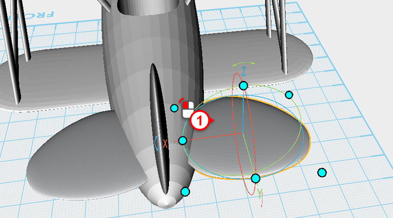
This tutorial’s scope covers how to use XYZmaker to make an excavator, and use the modeling tools to create articulated parts. For example, after putting all the parts together you will have made an excavator that will be able to move its scoop and arm. Because XYZmaker is targeted towards beginner modelers, we can only use the modeling features to create a basic structure, adjust the proportions according to your preferences, to create a unique 3D model. The excavator individual part groups are a little complicated, because of this, the model has been divided into various parts. These are: body, track, Chassis, boom, digging arm, bucket and other blocks. Individually create the parts and save them, then lastly take all the parts and combine them together, to finish a complete excavator 3D model. After collecting all of the reference material , hand draw or use graphic software to draw the outline

Read more
XYZmaker tutorial – the Excavator part 2

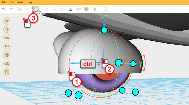
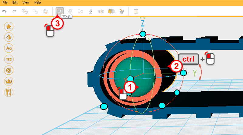
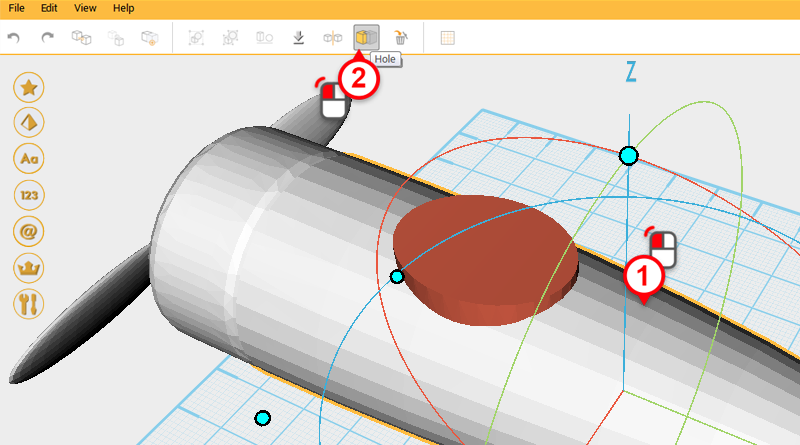
After completing the track frame, continue to make the internal structure of the track. Create a cylinder and rotate it 90 ° along the Y axis, then change the dimensions to X: 25,Y: 20,Z: 20 mm and position to X: 0,Y: -55,Z: 14.   Clone the cylinder and change its dimensions to X: 25,Y: 18,Z: 18 mm and position to X: 22,Y: -55,Z: 14. Call this part the cutting part.   Use the cutting part and the Hole function to cut a recess into the cylinder.   Create a sphere and adjust its dimensions to X: 6,Y: 15,Z: 15 mm and position to X: 9,Y: -55,Z: 14.   Select the cylinder and sphere and click in the Group button, to finish the big wheel.   Clone the big wheel and change its Y axis position to 55.   Create a cylinder and rotate it 90° along the Y axis, change the dimensions to X: 20,Y: 8,Z: 8 mm and position to X:

Read more

XYZmaker tutorial – the Excavator part 3

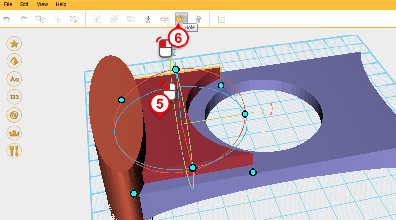
Next you want to make the chassis using the dimensions from the two tracks we just created. The left and right track’s dimensions are 70mm apart, 138mm long, and 28mm high. Use these measurements as a reference when creating the chassis. Create a cube and change its dimensions to X: 70,Y: 120,Z: 15 mm and position to X: 0,Y: 0,Z: 7.5. Call this part the chassis.   The front of the chassis has a concave recess. Create two cylinders, select one and change its dimensions to X: 75,Y: 20,Z: 30 mm and move it to the following position, X: 0,Y: -63,Z: 10.   Change the other cylinder’s dimensions to X: 75,Y: 20,Z: 30 mm and move it to the back by changing its position to X: 0,Y: 63,Z: 10.   Use the two cylinders and the hole function to cut away two recesses from the base as shown in the image above.   Next you need to cut

Read more

XYZmaker tutorial – the Excavator part 4

To start making the body, first create a cube and change its dimensions to X: 100,Y: 110,Z: 5 mm and position to X: 0,Y: 0,Z: 2.5. Call this part the floor.   Create another cube and change its dimensions to X: 100,Y: 40,Z: 35 mm and position to X: 0,Y: 60,Z: 17.5. Call this part the engine.   Create a cylinder and change its dimensions to X: 100,Y: 10,Z: 5 mm and position to X: 0,Y: -55,Z: 2.5. This will add a front edge to the floor.   Create another cylinder and change its dimensions to X: 100,Y: 10,Z: 35 mm and position to X: 0,Y: 55,Z: 17.5. This will add a rear curve to the floor and engine.   Create a cube and change its dimensions to X: 42,Y: 34,Z: 8 mm and position to X: 24,Y: 38,Z: 36.   Create another cube and change its dimensions to X: 42,Y: 22,Z: 4 mm and position to X: -24,Y: 44,Z:

Read more

XYZmaker tutorial – the Excavator part 5

After adding a contour to the driver cabin, continue and add a window. Clone the driver cabin and change the copied part’s dimensions to X: 40,Y: 64,Z: 46 mm. Take the newly created window contour and change its color to make the two parts easier to view.   Create three cubes and move them so that they surround the window contour as shown above.   From another angle look at the model so far, check that all of the part’s dimensions and positioning look like the image above.   Use the three cubes you just created and the Hole function to cut away a window shape.   Because after cutting away a window hole you will need a structure, select the window contour and click on the Clone button, this will create two window contours that overlap one another.   Select the driver cab and click on the Hole button, then select the window contour and click on the Hole

Read more

XYZmaker tutorial – the Excavator part 6

Before you start to make the boom, first in a 2D image plan how the excavator boom will be assembled. As shown in the image above, separate the structure into various shapes, and plan the location of the holes.   In XYZmaker open a new file and create a cube, adjust its dimensions to X: 17,Y: 20,Z: 90 mm and position to X: 0,Y: 0,Z: 60. Call this the boom.   Create a cube and change the dimensions to X: 30,Y: 20,Z: 110 mm and position to X: 0,Y: 25,Z: 60. Call this part the cutting part.   Select the cutting part and click and hold the arrow next to the Y axis in the control orb, then drag the arrow down with the mouse while holding ctrl and rotate the part to 357 ° Tip:Drag the mouse then hold down the ctrl key to rotate in increments of 1°.   Change the cutting part’s Y axis

Read more

XYZmaker tutorial – the Excavator part 7

After completing the Boom part, add some more connecting features to the body part for connecting the boom to. Open the excavator_body.amf, click on the Menu bar then select File to use the Add item function.   In Add item window select excavator_boom.amf to add the Boom assembly to the excavator body assembly.   Select the boom assembly and change its position to X: -5,Y: -84,Z: 56.   As shown in the image above, first select the driver cab and move it to the back to make it easier to model the other parts.   Next, create the body and hydraulic connecting link, select the hydraulic assembly and click on the Ungroup button.   Select the cylinder shown in the image above and click on the Clone button. Next, change the cylinder’s dimensions to X: 6,Y: 13,Z: 13 mm and X axis position to -16.5. Tip:You can change the color of the parts when modeling anytime to make it easier

Read more

XYZmaker tutorial – the Excavator part 8

Before making the digging arm, you first need to set the boom’s position. To add the file excavator_boom.amf, go the Menu bar and under File, click on Add Item.   In Add item window select excavator_body.amf to add the body assembly to the excavator body assembly.   Select the boom assembly and change the position to X: -5,Y: -84,Z: 86.66.   Drag select all the parts and with ctrl button pressed, click on the boom assembly to remove it from the selection. Click on the Delete button or press the delete key to delete the body.   Save the remaining Boom assembly.   When modeling the digging arm and the boom, first make a 2D drawing to plan out the shapes needed to model the part and at the same time plan the different hole positions.   Because the digging arm and boom both have elements in common, you can use the boom model as a base when making the digging arm.

Read more

XYZmaker tutorial – the Excavator part 9

Next continue making the excavator bucket. Create a Half pie part and rotate it 90 ° along the Z axis, then again 95 ° along the X axis. Call this part the bucket.   Change the bucket’s dimensions to X: 50,Y: 40,Z: 47 mm and position to X: -5,Y: -159,Z: 8.   Clone the bucket and call this part the cutting part. Change the cutting part’s dimensions to X: 45,Y: 40,Z: 42 mm and position to X: -5,Y: -157,Z: 8.65.   Use the cutting part and the Hole function to cut a cavity in the bucket.   Next make the teeth for the bucket, first you will make a larger part and after cutting the outside of the part, shrink it so that it fits with the bucket. Create a cube and change its dimensions to X: 40,Y: 80,Z: 15 mm and position to X: 0,Y: 0,Z: 7.5. This will be the teeth.   Create two cubes and adjust their dimensions,

Read more

XYZmaker tutorial – the Excavator part 10

There are two hydraulic rods that separate the top of the digging arm from the bucket, because of this you need to cut away room for the hydraulic rods. First open the excavator_arm.amf file, select the two parts shown in the image above and press the Group button.   Create a cube and change its dimensions to X: 3,Y: 40,Z: 20 mm and position to X: -5,Y: -150,Z: 142. Call this part the cutting part.   With the cutting part individually selected, click on the arrow next to the Y axis in the control orb, and drag the mouse down to rotate the part 345 degrees.   Use the cutting part and the Hole function to cut a trench in the top of the digging arm. Refer to image above.   After cutting you might notice part of the model protruding inside the trench similar to the area outlined in the image above.   Create another cube and use it to

Read more