XYZmaker tutorial – Robot Hand part 1
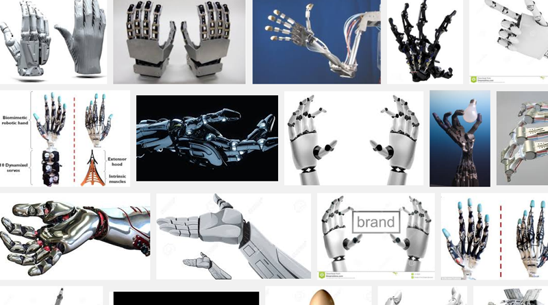
This tutorial uses XYZmaker to model basic 3D shapes, combine, and edit them – teaching you to create a functioning model of a robotic hand that is able to close and open. First collect some reference material and compare all the different types of robotic hands.

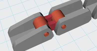
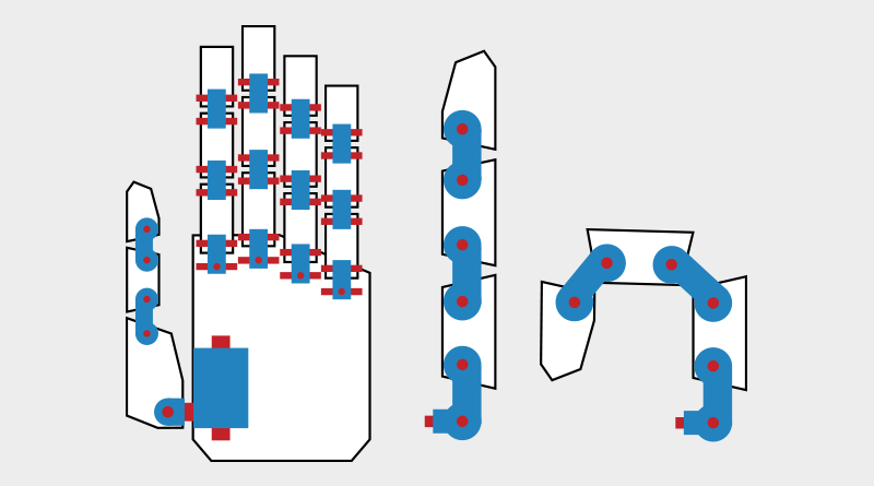
Next, using paper or sketching software, plan all the parts that you need to make and their individual rotation joints. After creating this reference drawing, use a chain-like structure for the joints, and give the finger links a bigger range of mobility. The blue parts in the image above are the joints, and the red parts will act as shafts that hold the pieces together.
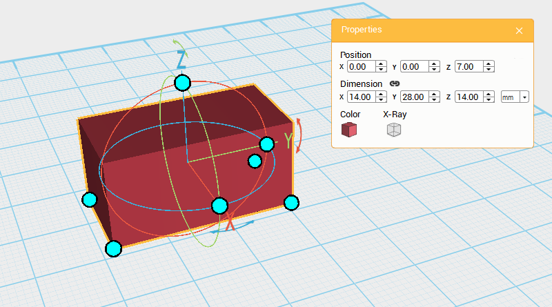
Create a cube and change its dimensions to X: 14,Y: 28,Z: 14 mm and position to X: 0,Y: 0,Z: 7. Call this part the Finger joint A.
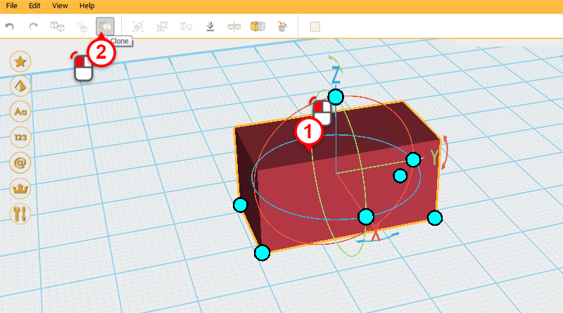
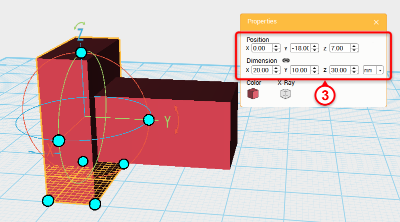
Select Finger joint A and click Clone. Next, change the dimensions to X: 20,Y: 10,Z: 30 mm, and position to X: 0,Y: -18,Z: 7. Call this the Cutting part
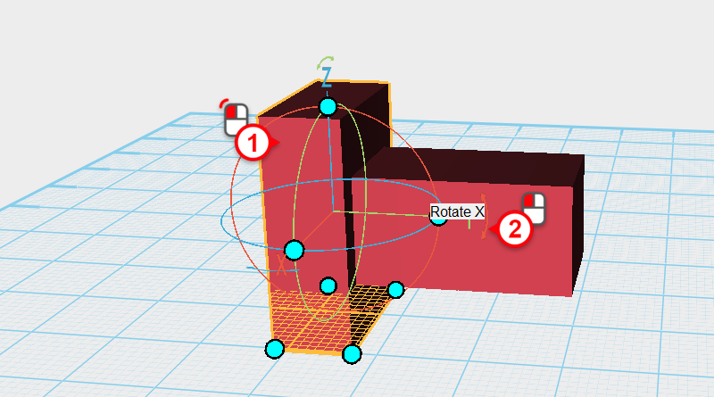
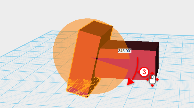
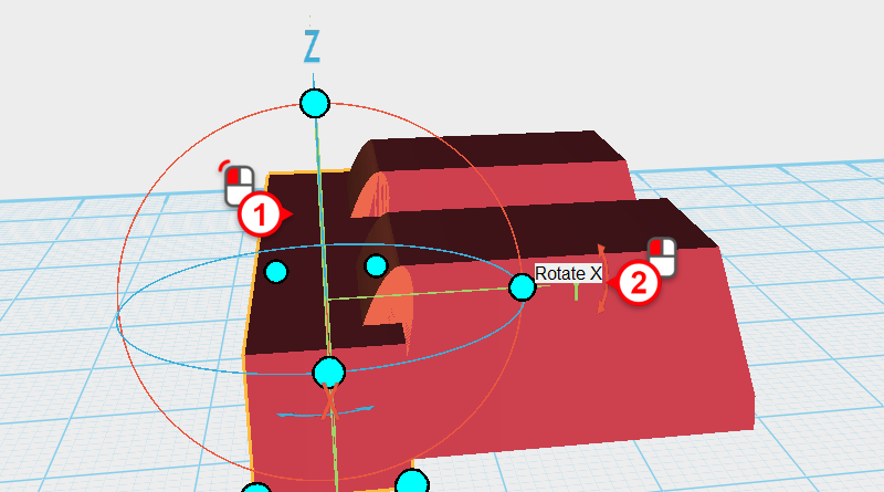
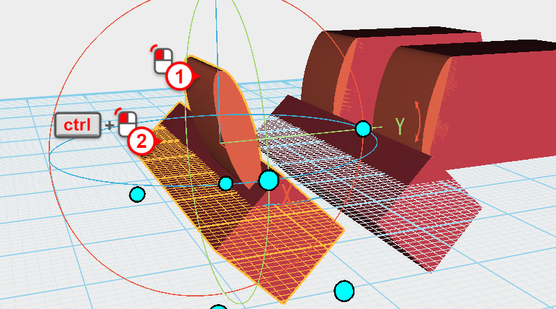
Select the Cutting part, then click and hold the arrow next to the Y axis in the bounding box, dragging the part and rotate it 345° .
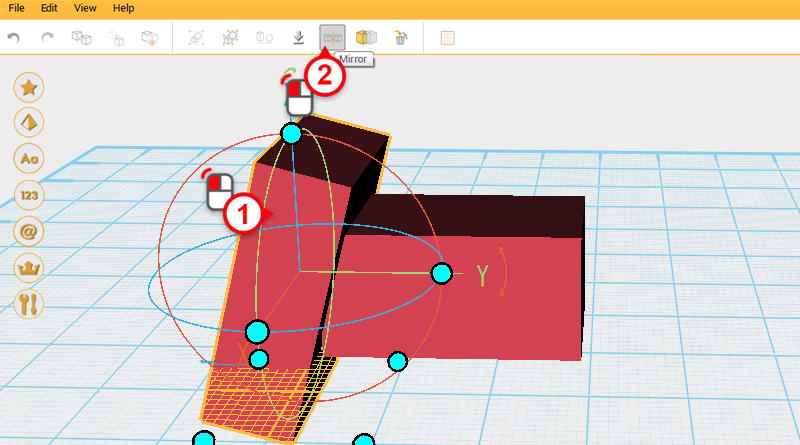
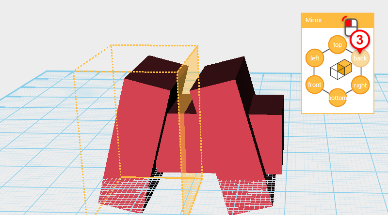
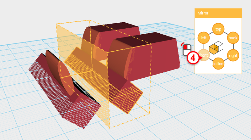
Select the Cutting part and click on Mirror. Next in the Mirror properties window click back.
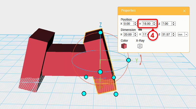
Select the Cutting part you just reflected, and change its Y axis position to 18.
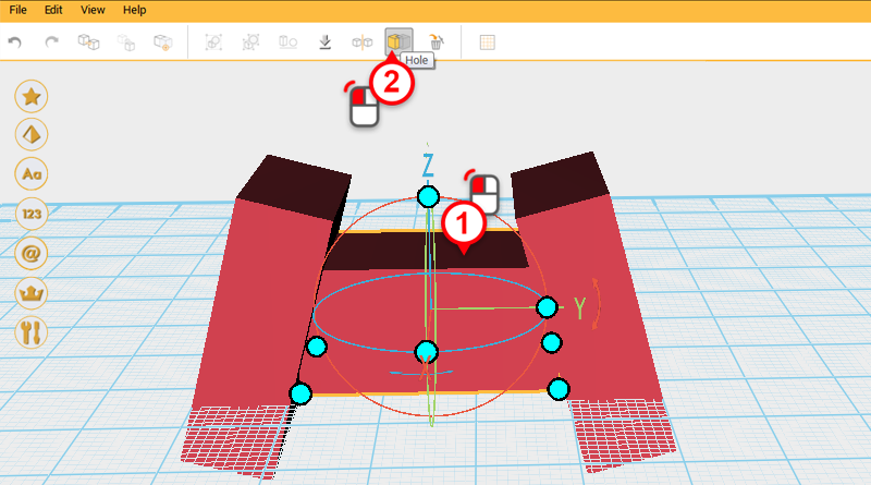
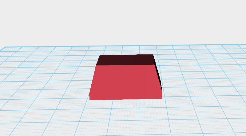
Use the two Cutting parts and the Hole function to cut a chamfer into the Finger joint as shown above.
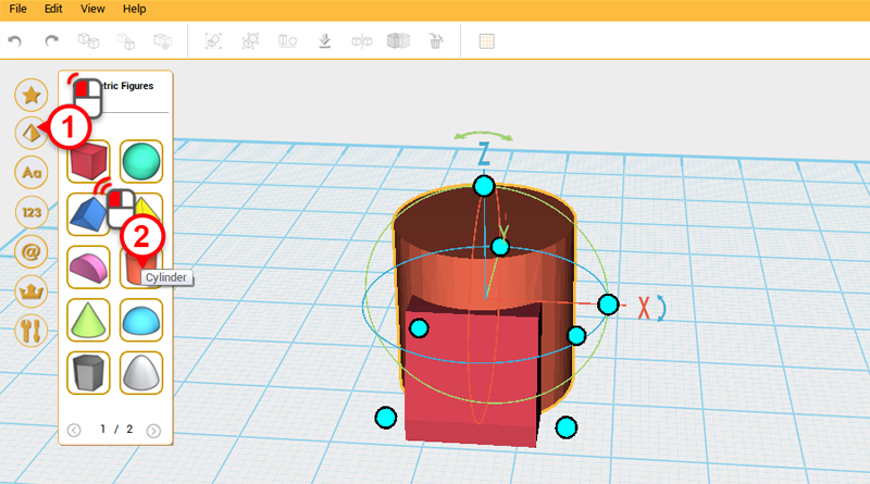
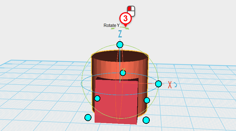
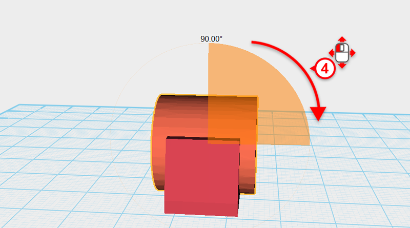
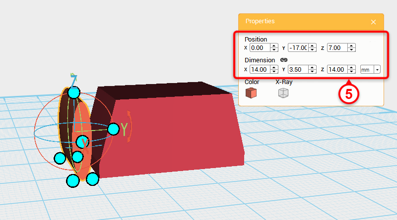
Create a Cylinder and rotate it 90° along the Y axis, then change its dimensions to X: 14,Y: 3.5,Z: 14 mm and position to X: 0,Y: -17,Z: 7.
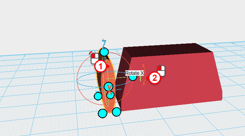
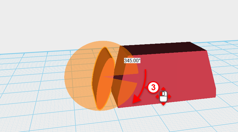
Select the Cylinder, then click and hold the arrow next to the Y-axis in the bounding box, dragging the part 345°.
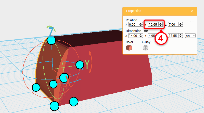
Next, change the Cylinder’s Y-axis position to -12.65.
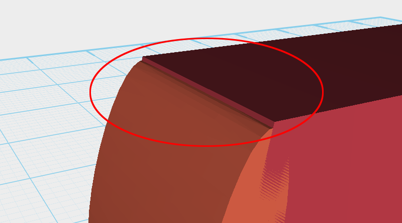
Zoom in and inspect the part, you will see an edge showing.
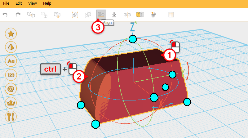
Select Finger joint A, then while holding down Ctrl, click on the Cylinder to select the two objects. Next, click on the Align button.
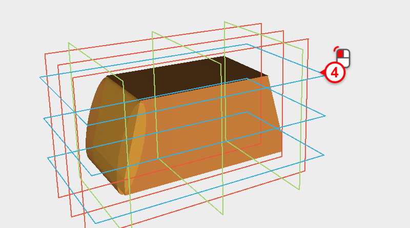
Click on the blue frame in the image to make the parts aligned.
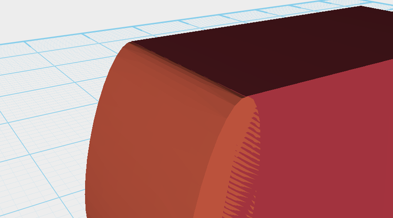
Zoom in on the part again and inspect it, you will see the gap has almost disappeared.
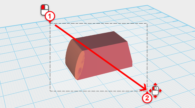
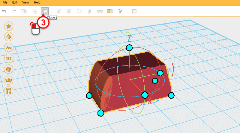
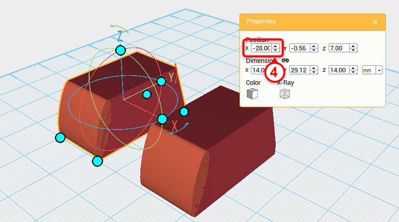
Drag select the parts shown above and click Clone. Next, change its X-axis position to -28.
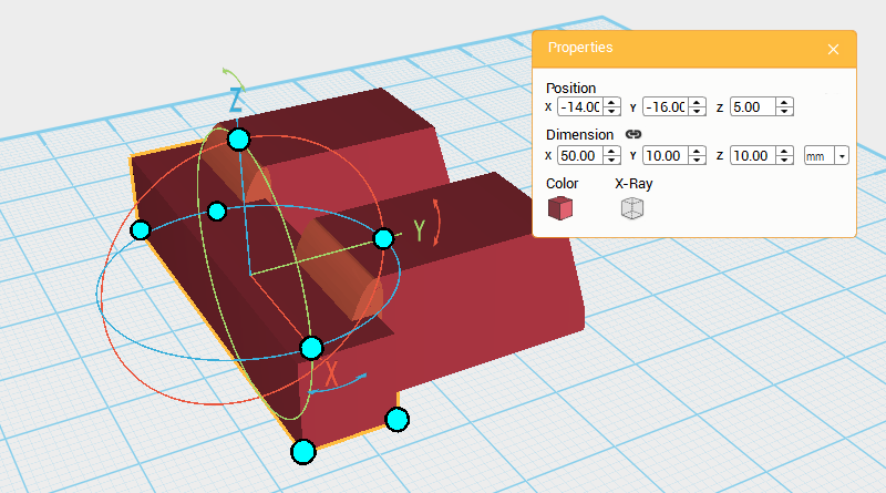
Create a Cube and change its dimensions to X: 50,Y: 10,Z: 10 mm and position to X: -14,Y: -16,Z: 5. Call this Cutting part.
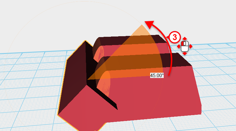
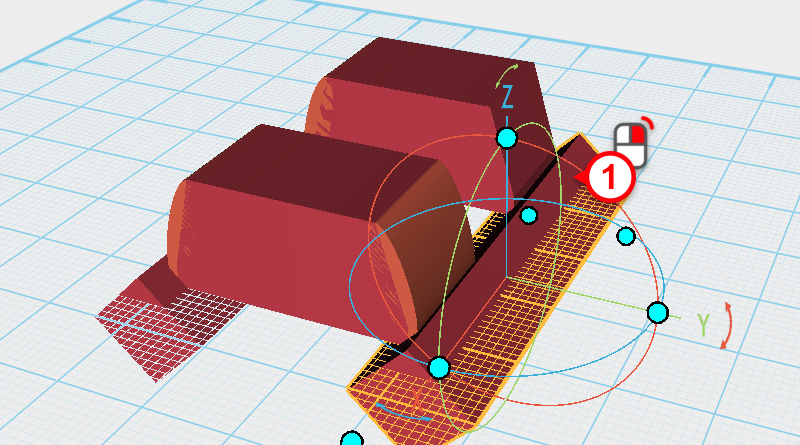
Select the Cutting part, then click and hold the rotation arrow next to the Y-axis in the bounding box, and rotate the part by 45°.
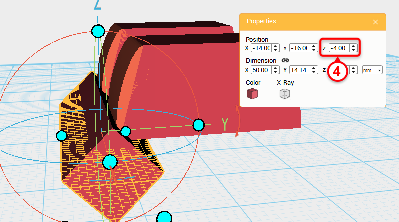
Next, change the Z-axis position to -4.
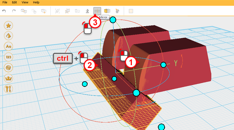
Select the two parts shown above and click Mirror. Next, in the Mirror properties box click front to reflect the part.
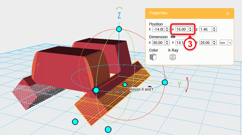
Select the two parts you just reflected and change their Y-axis position to 16.
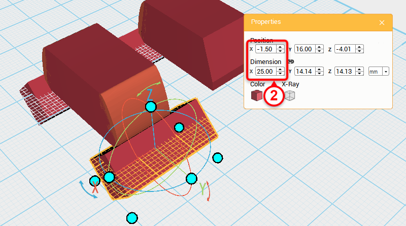
Select the cube shown in the image below and change its X-axis dimension to 25, and X-axis position to -1.5.
Now the part’s placement should look as above.
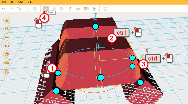
Select the three parts shown in the image above and click Group. Call this Finger joint A.
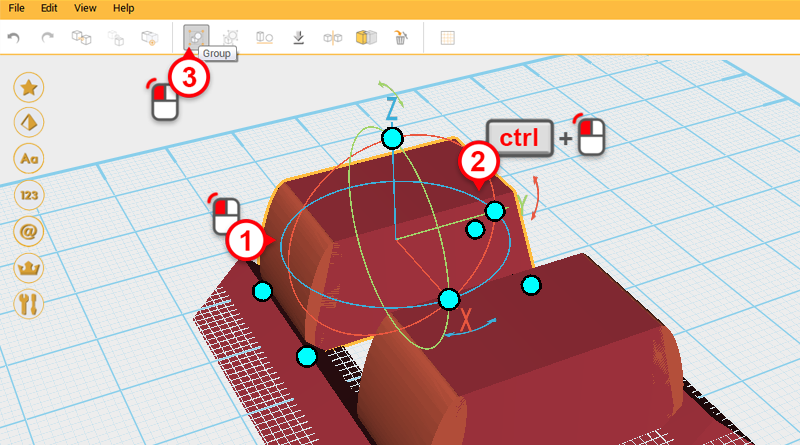
Select the two parts shown above and click Group. Call this part Fingertip.
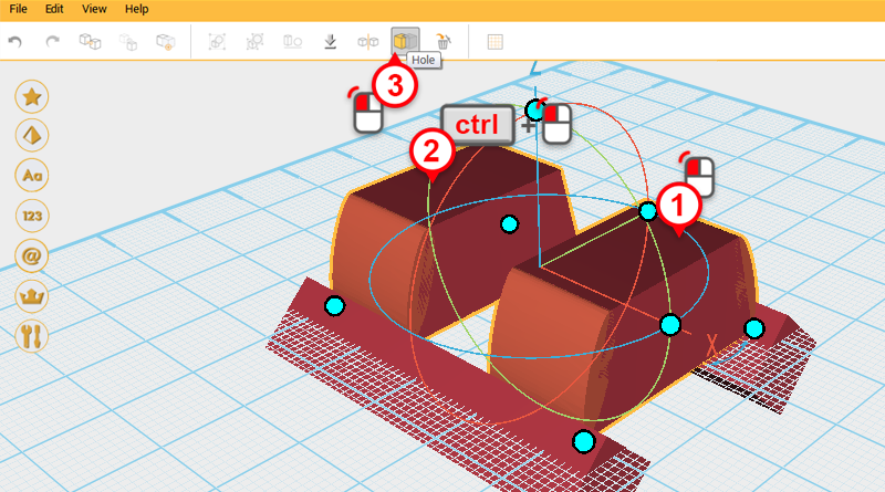
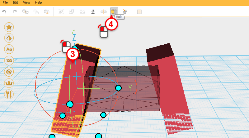
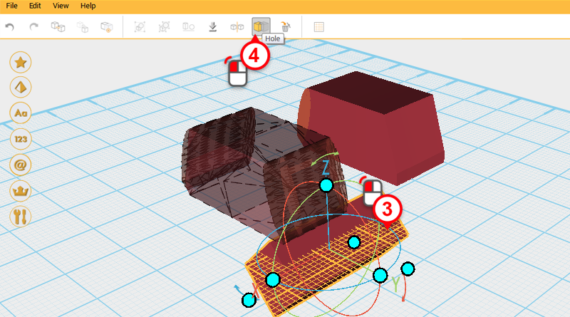
Select Finger joint A, hold down ctrl, and add Fingertip to the selection. Next, click on Hole.
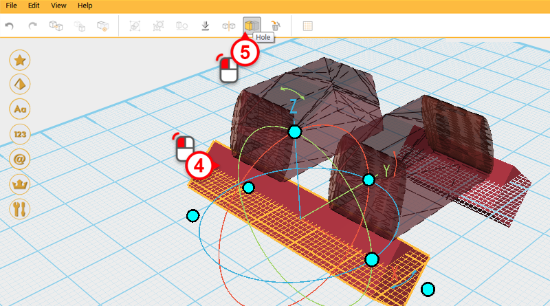
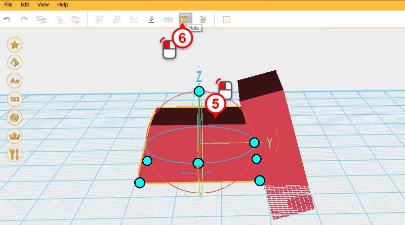
Select the Cutting part in the image above and click on Hole again.
Select Finger joint A and click on Hole.
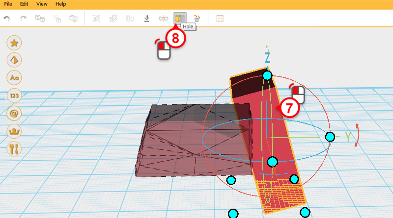
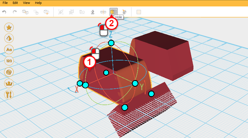
Select the Cutting part shown above and click on Hole again to finish cutting the side.
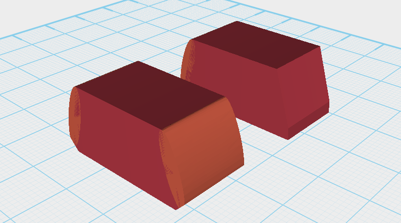
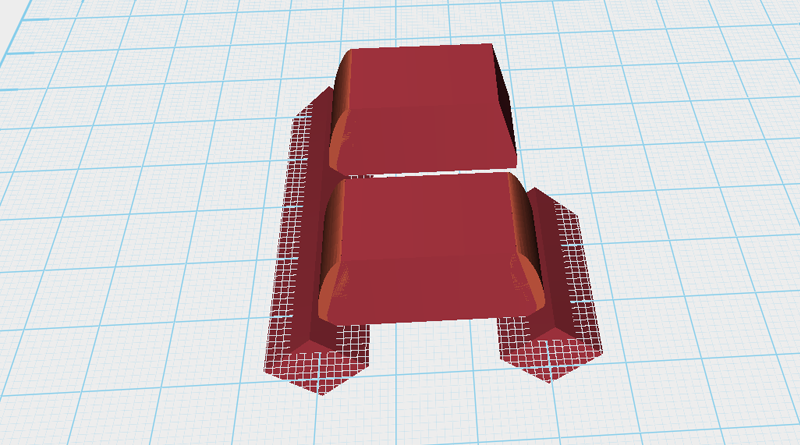
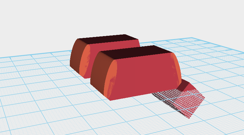
After cutting is complete your model should resemble the image above.