XYZmaker tutorial – Robot Hand part 3
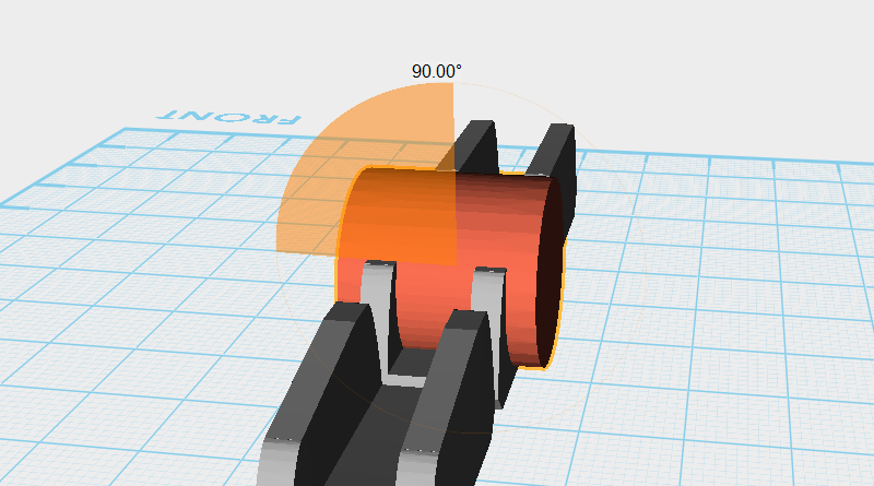
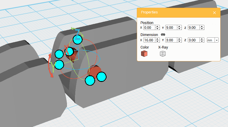
Create a Cylinder and rotate it 90° along the Y-axis, then change its dimensions to X: 16,Y: 3,Z: 3 mm and position to X: 0,Y: 9,Z: 9. This will be used as a rotation anchor point.
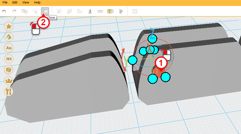
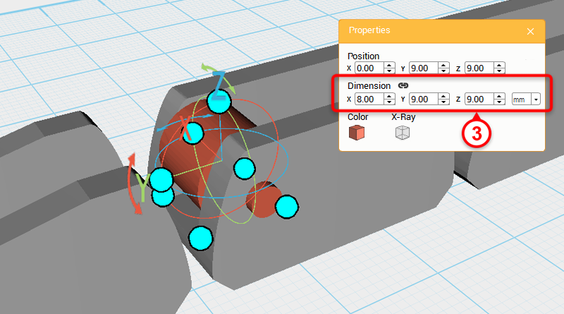
Select the Cylinder you just created and click on Clone to duplicate another Cylinder. Change this new part’s dimensions to X: 8,Y: 9,Z: 9 mm.
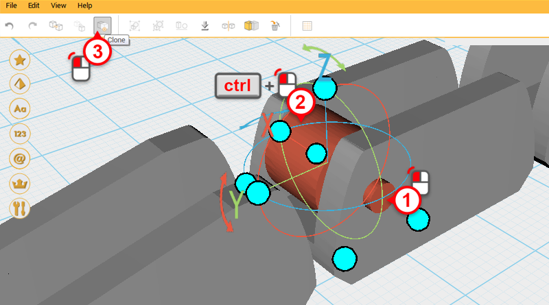
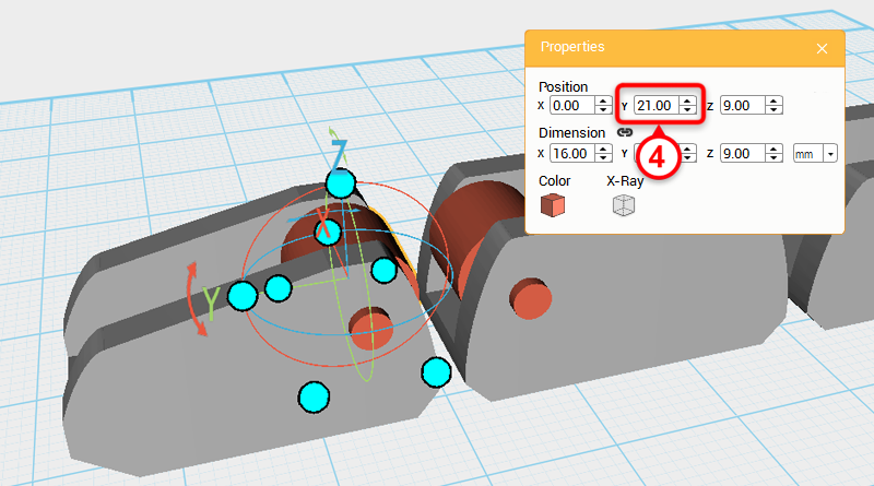
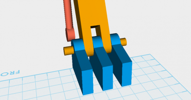
Select the two Cylinders shown in the image above, click Clone, and change the parts Y-axis position to 21.
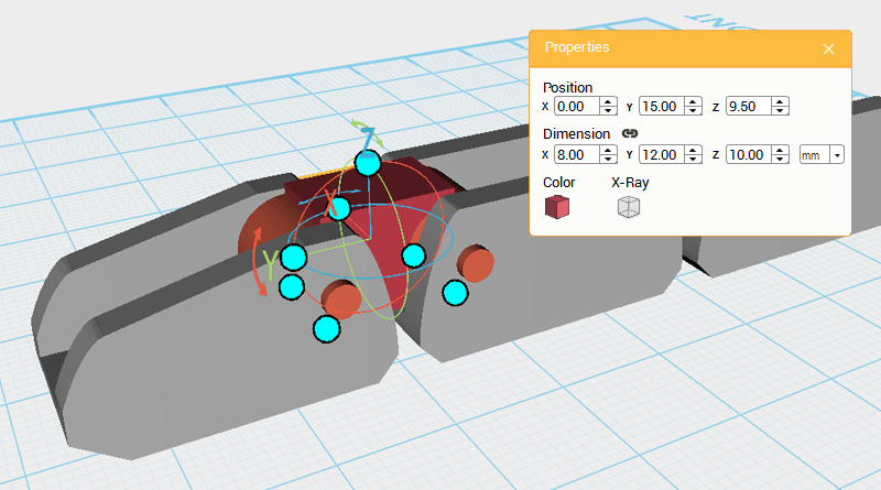
Create a Cube and change its dimensions to X: 8,Y: 12,Z: 10 mm, and position to X: 0,Y: 15,Z: 9.5.
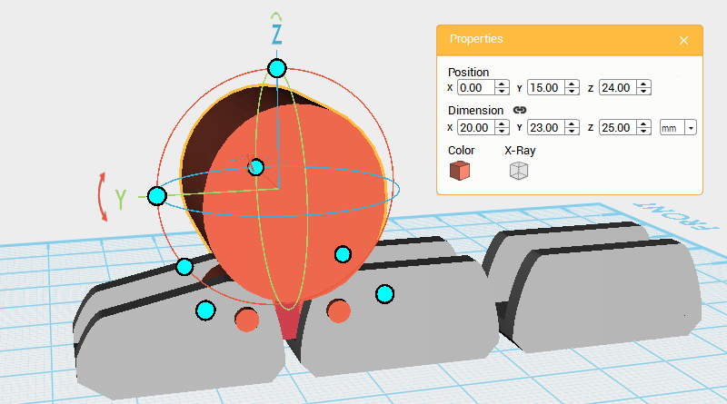
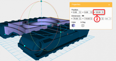
Create a Cylinder and rotate it 90° along the Y-axis, change its dimensions to X: 20,Y: 23,Z: 25 mm, and position to X: 0,Y: 15,Z: 24.
Select the Cube and click on Hole.
Select the Cylinder and click Hole again.
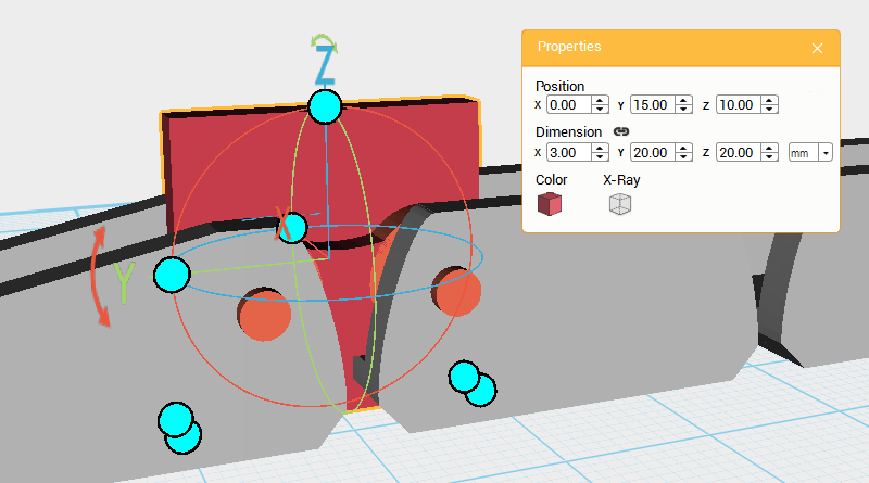
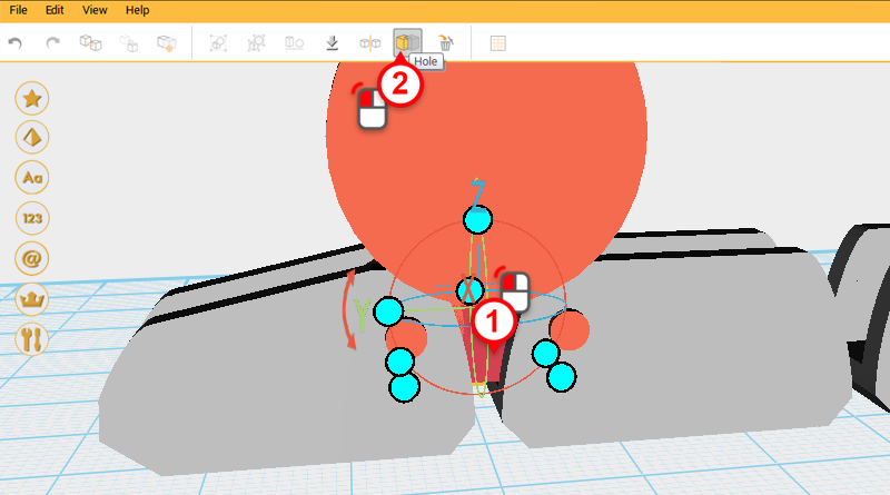
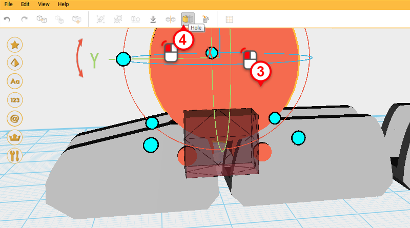
Create a Cube and change its dimensions and position as shown in the image above. Call this the Cutting part.

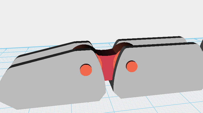
Next use the Cutting part and Hole function to cut away from the original Cube as shown above. This will give the part a more detailed feel.
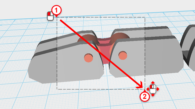
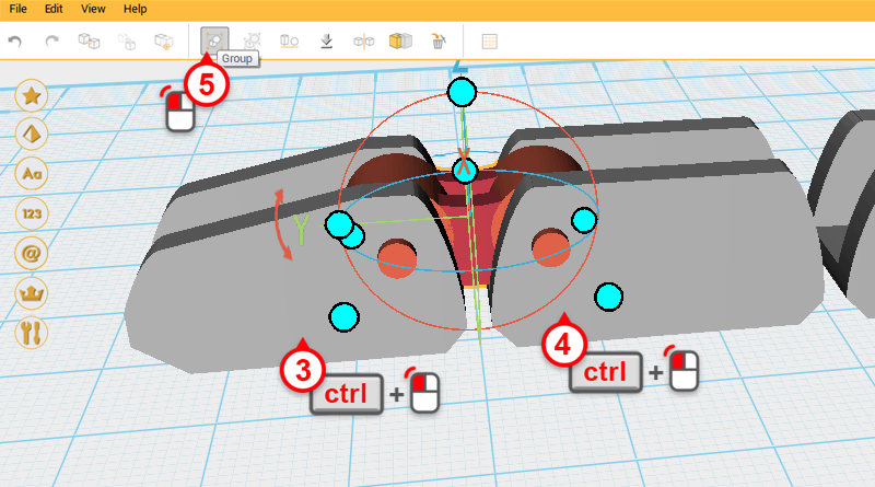
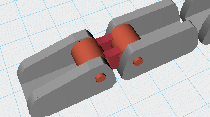
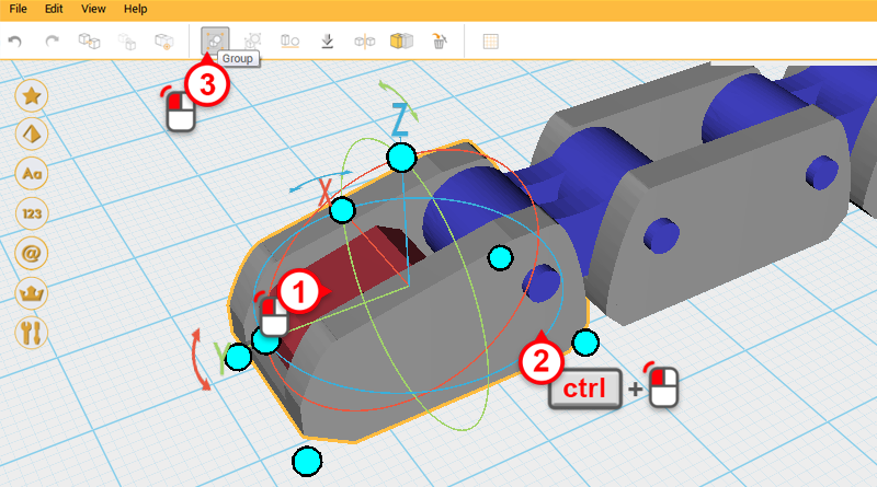
Drag select the parts as shown above, then hold down ctrl and click on the Fingertip and Finger joint A to deselect them. Lastly, click Group to finish the Knuckle.
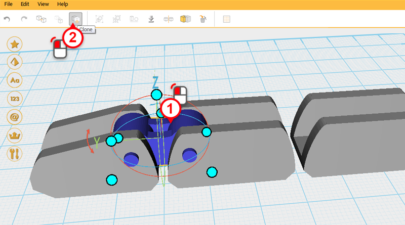
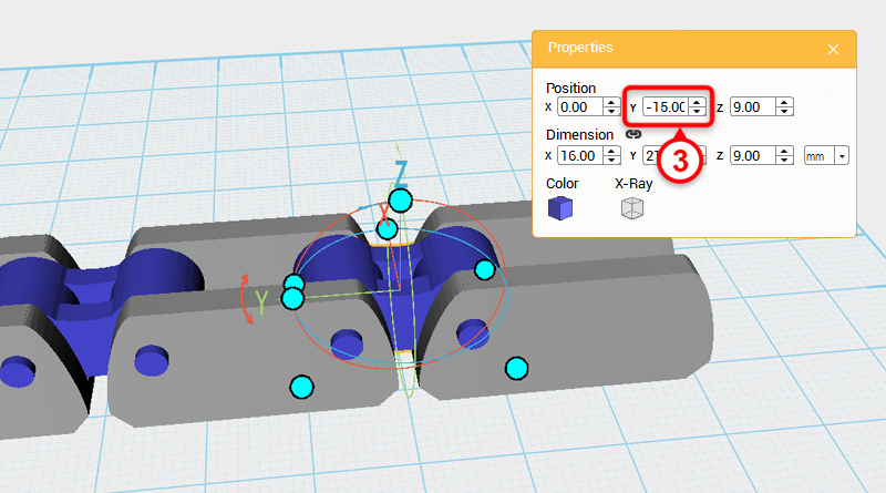
Select the Knuckle, click on Clone, and change the new part’s Y axis position to -15.
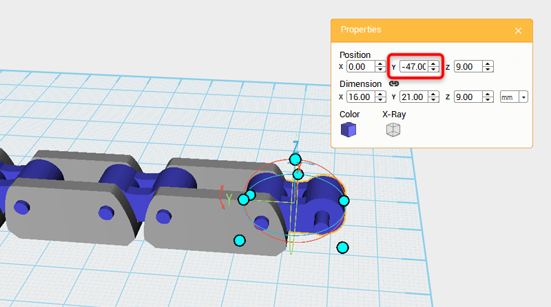
Repeat the steps above and clone the Knuckle again. This time change the new part’s Y-axis dimension to -47.
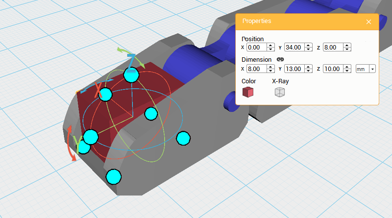
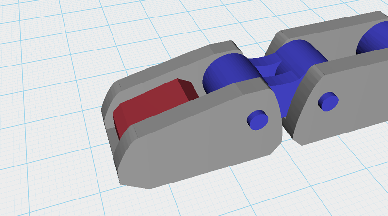
Inspect the you progress and you will see the Fingertip is too hollow. Because of this, we need to fill the inside of the Fingertip in. Create a Cube and change its dimensions to X: 8,Y: 13,Z: 10 mm and position to X: 0,Y: 34,Z: 8.
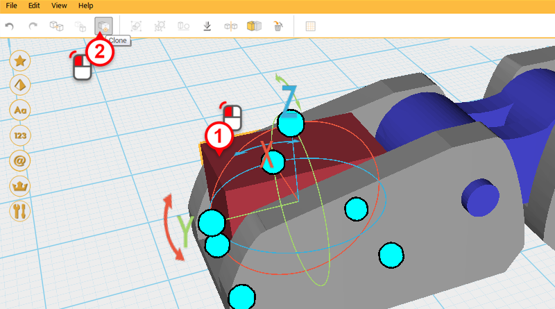
Select the Cube and click Clone. Next, change the parts dimensions to X: 10,Y: 20,Z: 10 mm and position to X: 0,Y: 34,Z: 15. Call this the Cutting part.
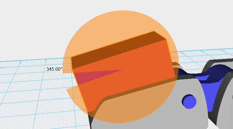
Select the Cutting part and rotate it along the X-axis as shown above.
Use the Cutting part and the Hole function to cut a slope in the Cube as shown above.
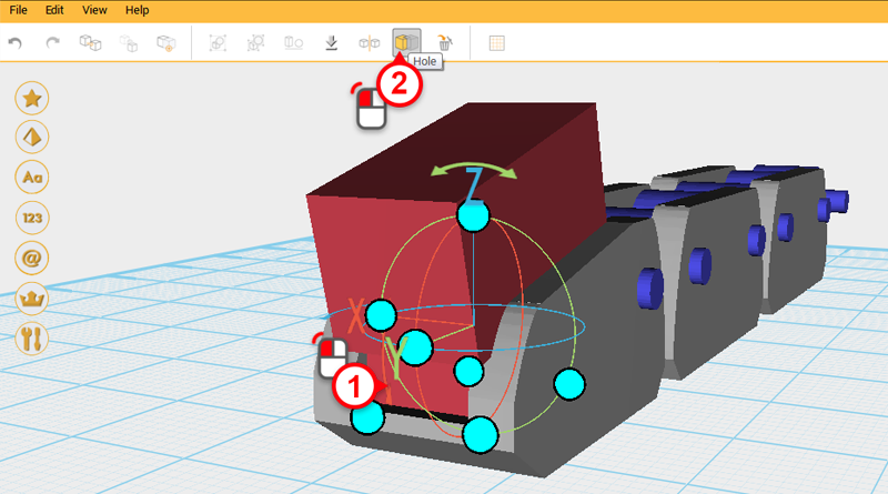
Create a Cube and change its dimensions to X: 10,Y: 20,Z: 12 mm and position to X: 0,Y: 43,Z: 13. Call this part the Cutting part.
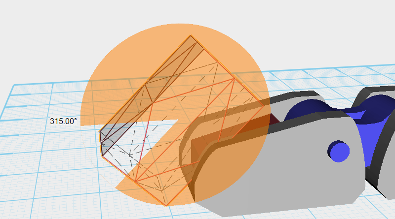
Select the Cutting part and as shown above, rotate the part along the X-axis.
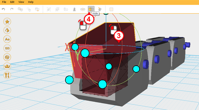
Use the Cutting part and the Hole function to cut a chamfer into the Cube.
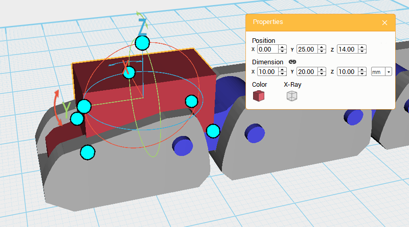
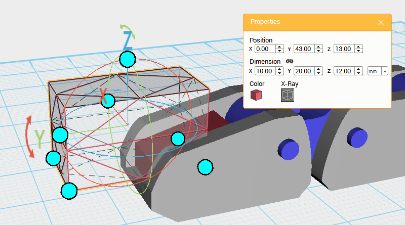
Create a Cube, change its dimensions to X: 10,Y: 20,Z: 10 mm, and position to X: 0,Y: 25,Z: 14. Call this past the Cutting part.
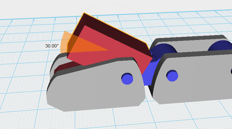
Select the Cutting part and as shown above, rotate the part along the X-axis.
Use the Cutting part and the Hole function to cut a chamfer into the Cube.
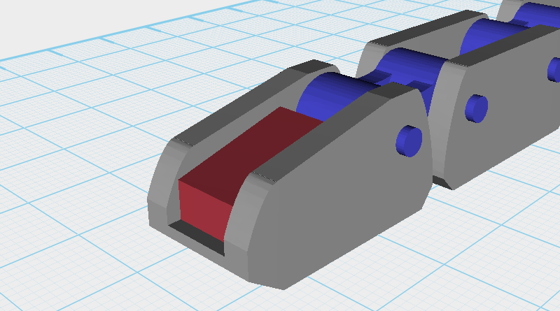
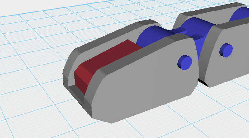
Select the Fingertip and the newly trimmed Cube then click Group.
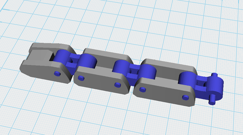
So far the finger assembly should look as above. Call this assembly the Index finger. Going forward, we should be able to use this model as a basic model for the remaining fingers.