XYZmaker tutorial – Robot Hand part 7
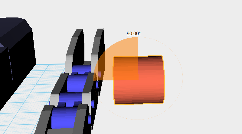
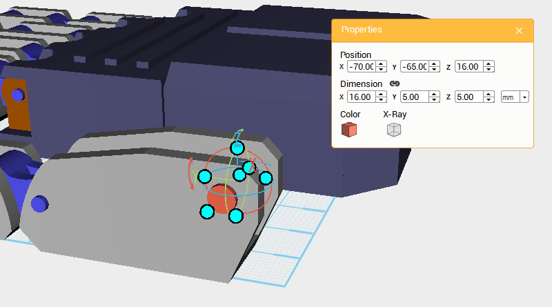
Next, create the joint that connects the Thumb and Palm. Create a Cylinder and rotate it 90° along the Y-axis then change the part’s dimensions to X: 16,Y: 5,Z: 5 mm and position to X: -70,Y: -65,Z: 16.
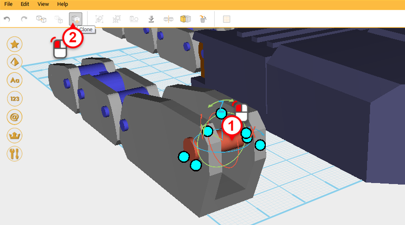
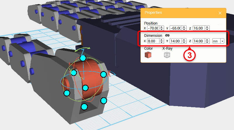
Select the Cylinder and click Clone. Change the new part’s dimensions to X: 8,Y: 14,Z: 14 mm.
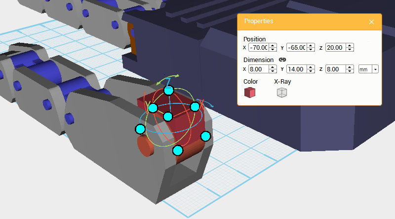
Create a Cube and change its dimensions to X: 8,Y: 14,Z: 8 mm and position to X: -70,Y: -65,Z: 20.
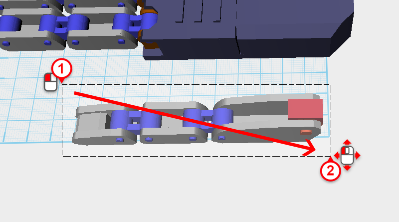
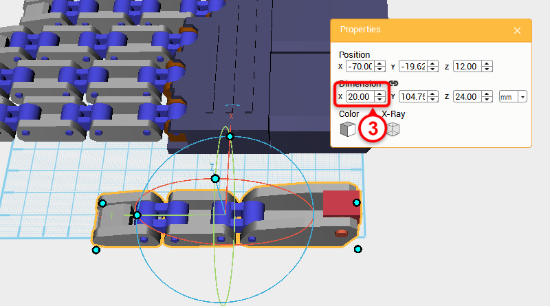
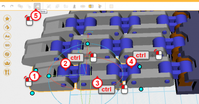
Next, take the Thumb and make it thicker; drag select the parts as shown above, then change their X-axis dimension to 20mm.
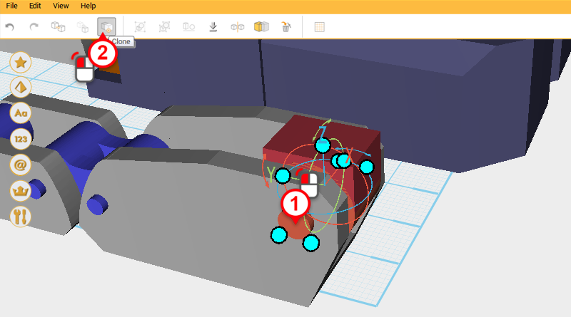
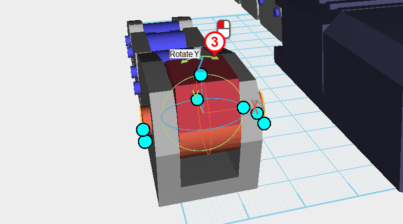
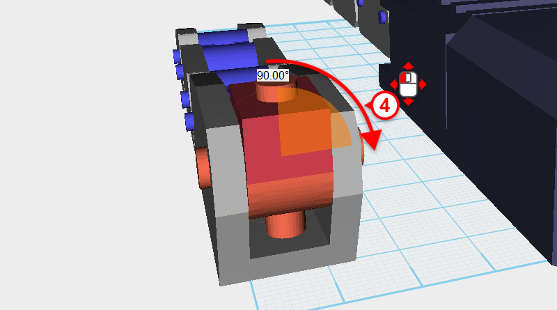
Select the Cylinder in the image above and click Clone. With the new part, click and drag the arrow next to the Z-axis in the bounding box of the new part, and rotate the part 90°.
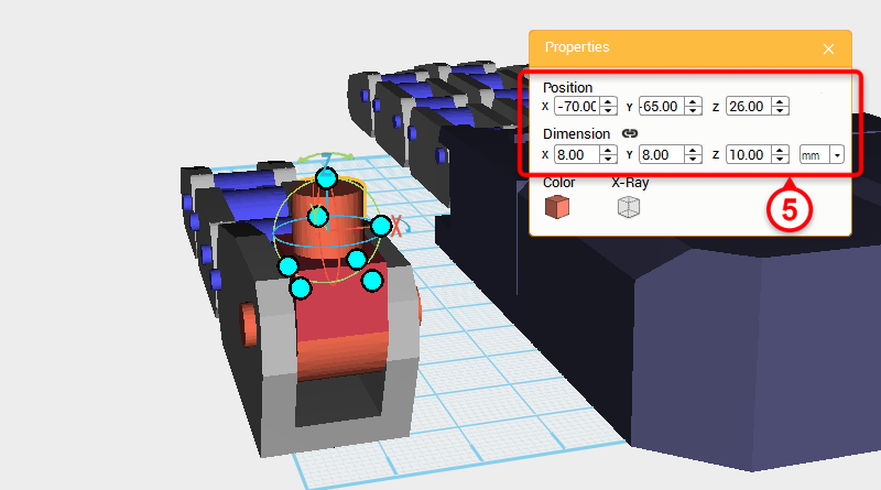
Lastly, take the Cylinder and change its dimensions to X: 8,Y: 8,Z: 10 mm and Z-axis position to 26.
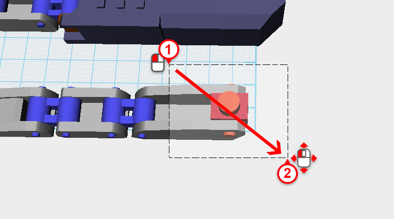
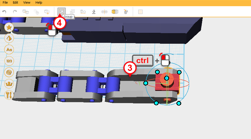
Drag select the parts shown in the image above, then while holding down ctrl , individually deselect the parts of the Thumb base and click Group.
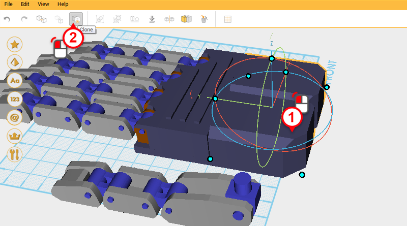
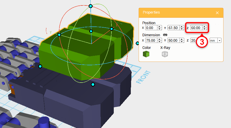
The Palm and Thumb joint need a connector.Select the Palm and click Clone; change the new part’s Z-axis position to 60, and call it the Thumb base connector. At the same time change the part’s color so it is easier to recognize.
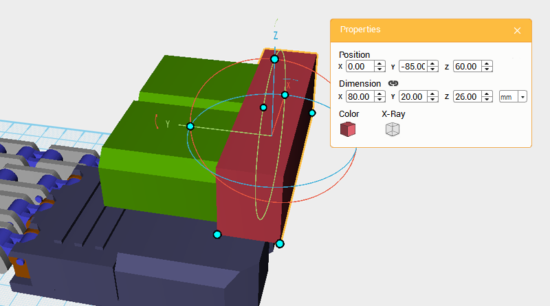
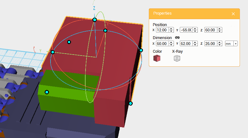
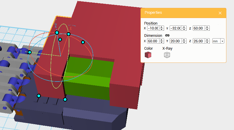
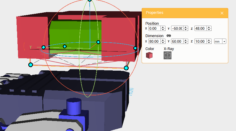
Create four Cubes, and make their positions and dimensions the same as the image above. Use these as Cutting parts.
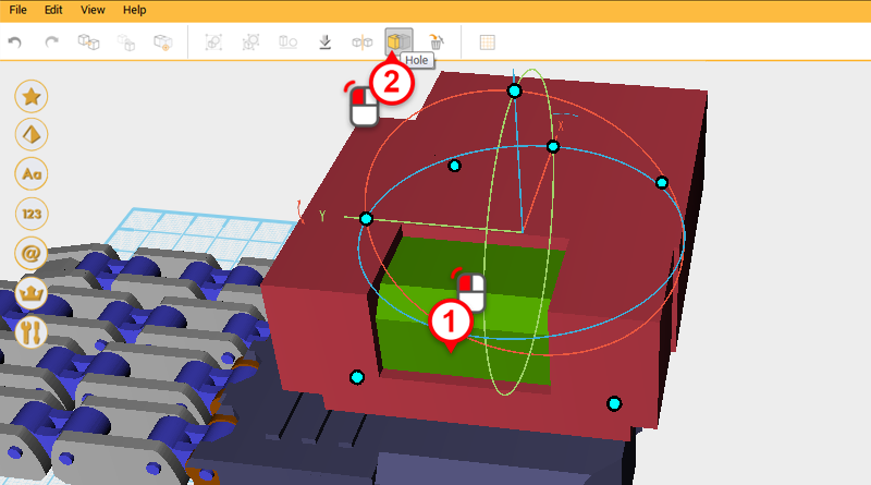
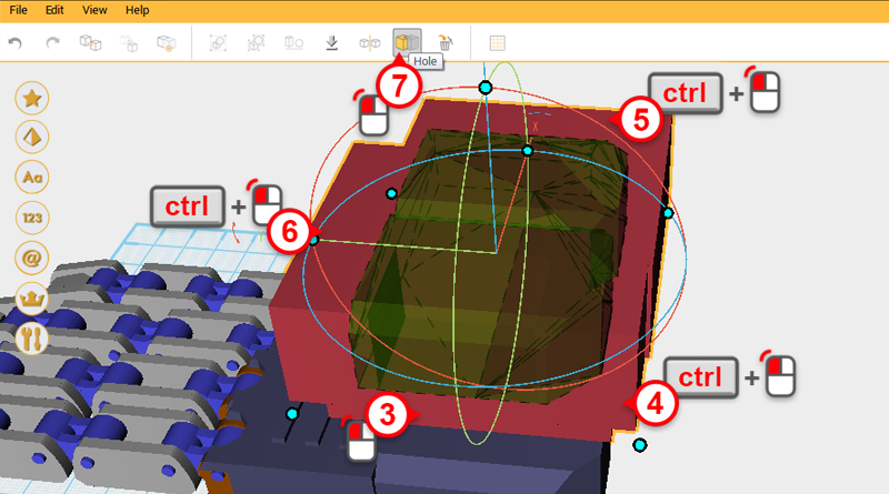
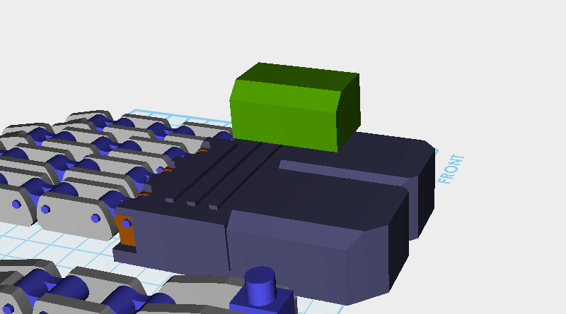
Use the four Cutting parts and the Hole function to cut away the sides of the Thumb base connector.
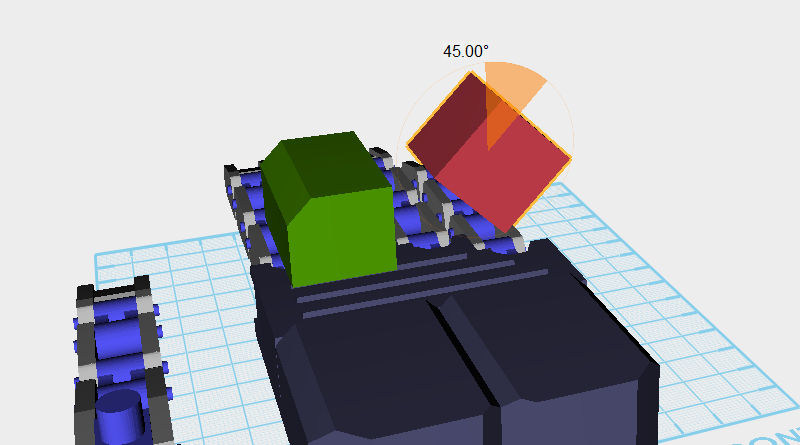
Keep trimming the Thumb base connector so that when it rotates it won’t jam. Create a Cube and move it closer to the Thumb base connector, then rotate the part 45° along the Y-axis. Call this the Cutting part.
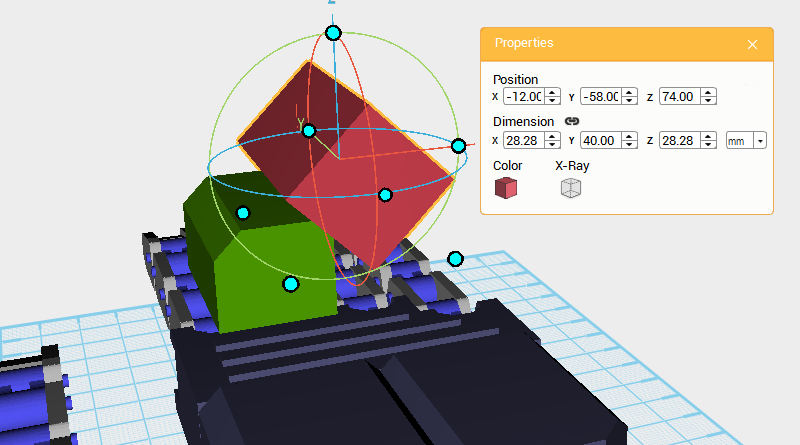
Select the Cutting part and change its Y-axis dimension to 40 and position to X: -12,Y: -58,Z: 74.
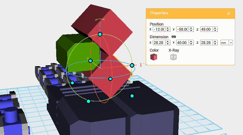
Clone the cutting part and change its Z-axis position to 49.
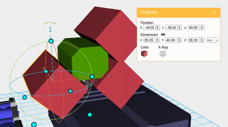
Clone the Cutting part again and change its X-axis position to -44 and Z-axis position to 49.
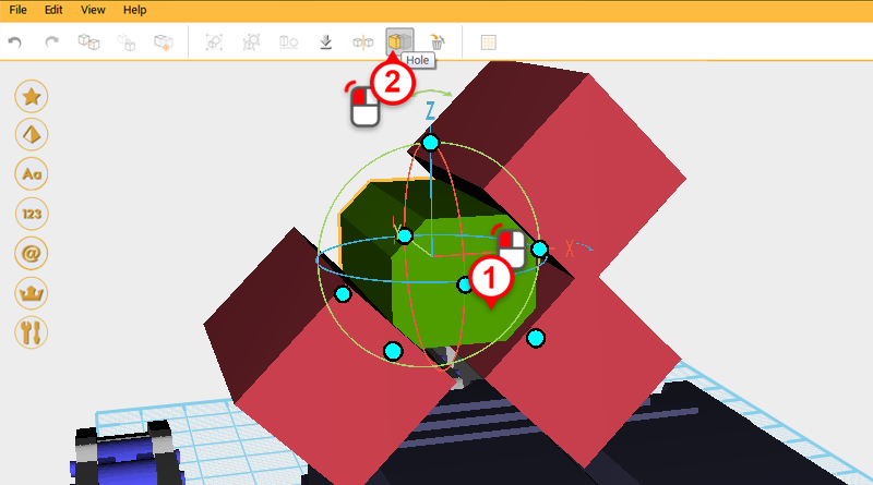
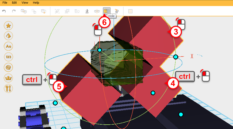
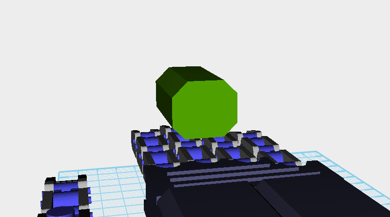
Use the three Cutting parts and the Hole function to cut into the Thumb base connector.
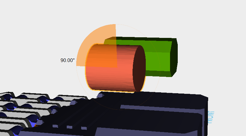
Create a Cylinder and move it near to the Thumb base connector. Rotate the part 90° along the X-axis.
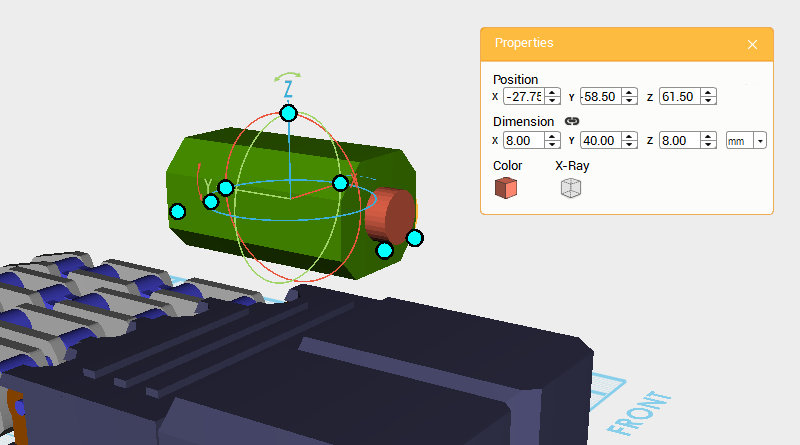
Change the Cylinder’s dimensions to X: 8,Y: 40,Z: 8 mm and position to X: -27.75,Y: -58.5,Z: 61.5.
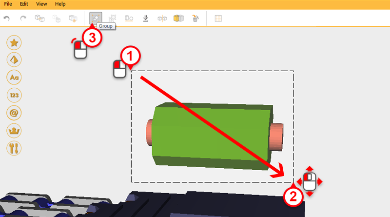
Drag select the part above and click Group to complete the Thumb base connector.
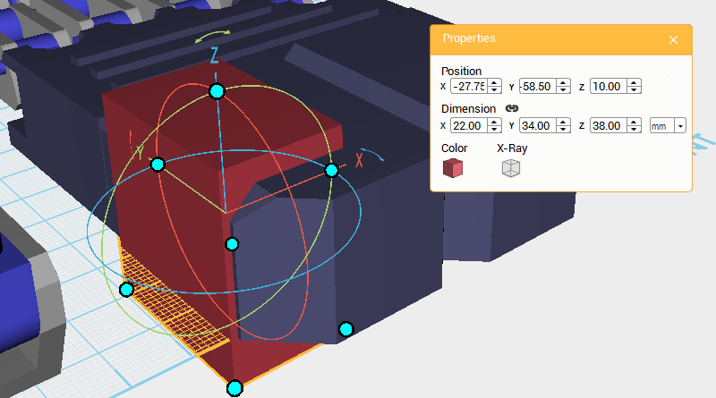
Next, you need to cut out an area for the Thumb base connector to sit in the Palm center. Create a Cube and change its dimensions to X: 22,Y: 34,Z: 38 mm and position to X: -27.75,Y: -58.5,Z: 10. Call this the Cutting part.
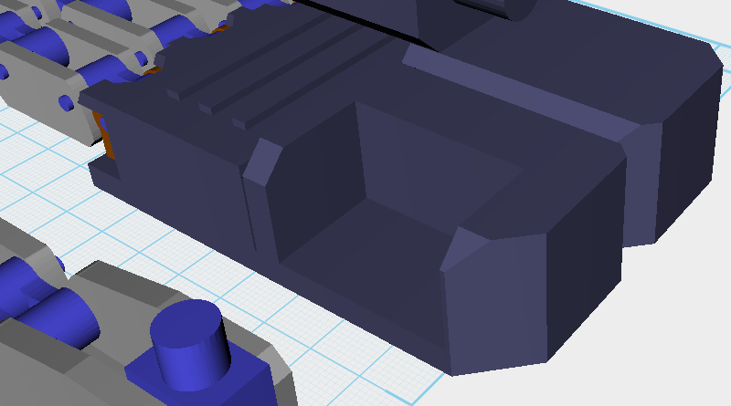
Use the Cutting part and the Hole function to cut away from the Palm center.
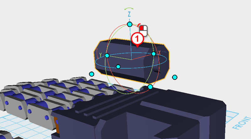
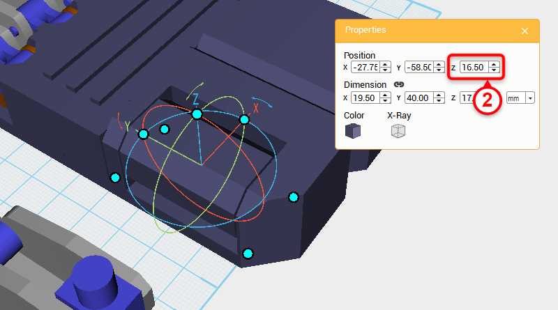
Select the Thumb base connector and change its Z-axis position to 16.5.
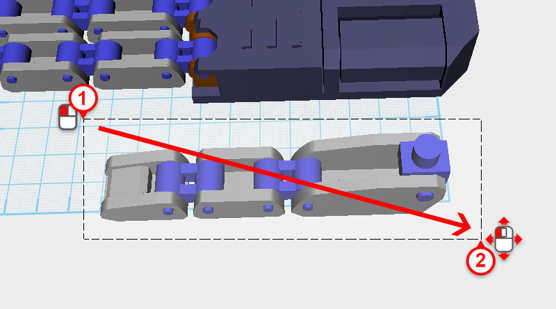
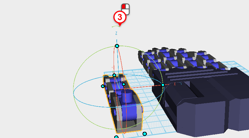
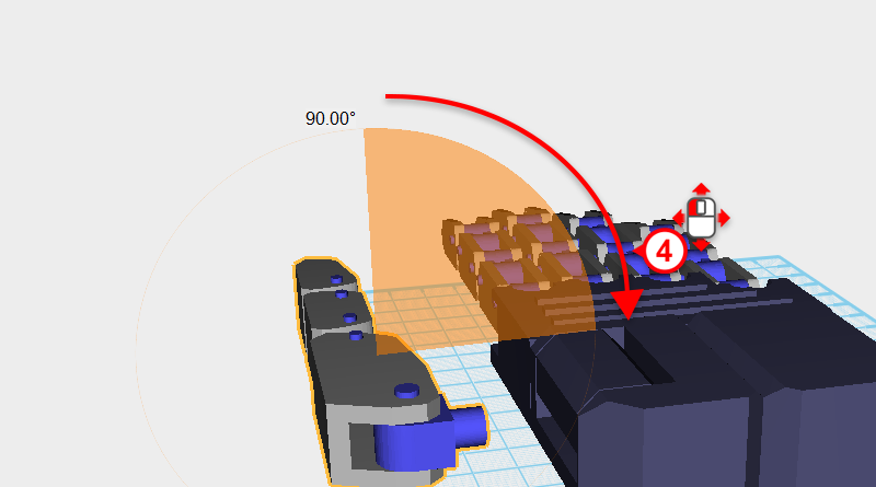
As shown above, drag select all the Thumb components, then click and drag the arrow next to the Z-axis in the bounding box and rotate the selection 90°.
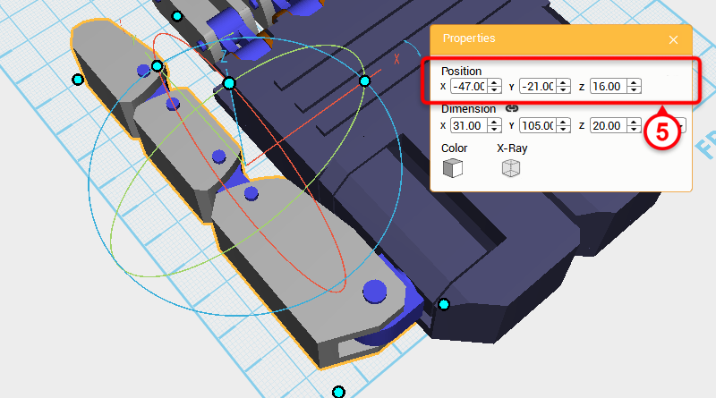
Lastly change the selection’s position to X: -47,Y: -21,Z: 16, to connect the Thumb and Palm together.
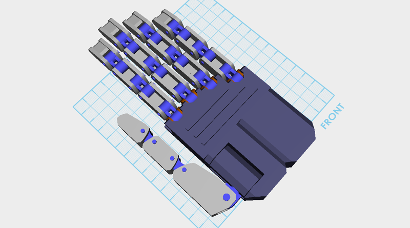
So far your model should resemble the image above.

