XYZmaker tutorial – Airplane part 1

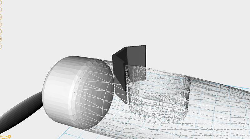
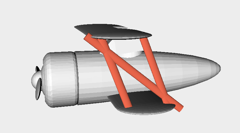
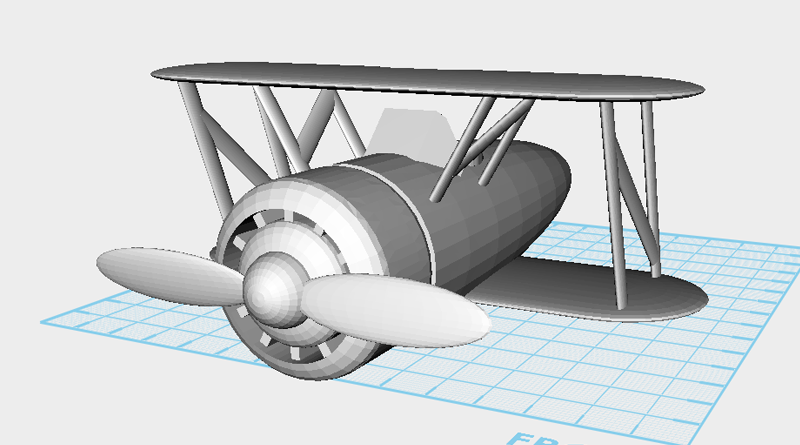
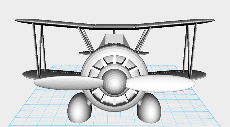
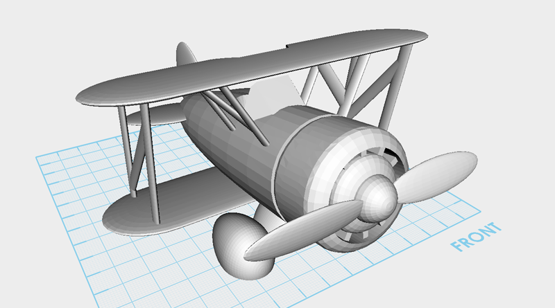
Go to the Geometric figures library and create a paraboloid. Rotate the part 270 ° along the X-axis, and in the Properties window change the dimensions to X: 40,Y: 120,Z: 40 mm and position to X: 0,Y: 0,Z: 20. This part will be called the plane body. Tip: For instructions on rotating objects refer to the beginner tutorials.   Make a Capsule from the Geometric figures library, and rotate it 90° along the X-axis. In the Properties window change its dimensions to X: 40,Y: 30,Z: 40 mm and position to X: 0,Y: -70,Z: 20. This will be called the engine.   Create a Cylinder and rotate it 90° along the X-axis. In the Properties window change the dimensions to X: 30,Y: 20,Z: 30 mm and adjust the position to X: 0,Y: -80,Z: 20. This will be called the cutting part.   Select the engine and click on Hole, then click on

Read more

XYZmaker tutorial – Airplane part 2

Create a Hexagonal Prism and in the Properties window change the dimensions to X: 26,Y: 18,Z: 20 mm and position to X: 0,Y: -35,Z: 38. Call this part windshield.   Select the windshield and click on the Clone button; in the Properties window change the dimensions to X: 23,Y: 15,Z: 30 mm. Call this part the cutting part.   Select the windshield and click on the Hole button, then select cutting part and click on the Hole button again.   Create a cube, then in the Properties window adjust the dimensions to X: 30,Y: 20,Z: 40 mm and position to X: 0,Y: -25,Z: 35. Call this part cutting part.   Select the windshield and click on the Hole button, then select the cutting part and click on the Hole button again.   Select the windshield and click on the arrow above the Y-axis, move the mouse down to rotate the

Read more

XYZmaker tutorial – Airplane part 3

To create an airfoil, first make a sphere, then in the Properties window change its dimensions to X: 40,Y: 40,Z: 4 mm and position to X: 0,Y: -36,Z: 55.   Create a Cylinder and rotate it 90° along the Y axis, in the Properties window change the dimensions to X: 90,Y: 40,Z: 4 mm and position to X: 0,Y: -36,Z: 55   Select the Sphere you just created and click on the Clone button, change this new part’s X axis position to -45.   Drag select all parts and click on the Group button, to finish the upper wing part.   Select the plane body you just moved to the side and to return it to the center, change its X axis position to 0 .   Select the upper wing and click the Clone button.   In the Properties window adjust the new part’s position to X: 0,Y: -20,Z: 8. This

Read more

XYZmaker tutorial – Airplane part 4

Create a cube and enlarge the Z dimension value to 60mm. Next, rotate the cube 20° along the X axis and call it the cutting part. Change the center support’s color so we can see it more clearly.   Move the cutting part to the same position as shown in the image above. This will be used to cut the overhanging part of the support. Shown in the red circle above, this area is where you need to check the edge alignment of where the two supports intersect.   Select the cutting part and click on the Clone button, move the copied cutting part as shown in the image above. The same as before, this will be used to cut the overhanging part of the support so carefully check the edge alignment of where the two supports intersect.   When you zoom out, the plane should look as above.  

Read more

XYZmaker tutorial – Airplane part 5

Next to make a tail wing, create an Egg and in the Properties window change the dimensions to X: 4,Y: 34,Z: 38mm and position to X: 0,Y: 46,Z: 36. This part will be called the vertical tail wing.   Select the vertical tail wing then click and drag the arrow above the Y axis until you rotate the part 340°.   You can use the vertical tail wing to create the horizontal tail wing. Select the vertical tail wing and click on the Clone button, then click and drag the arrow above the Z axis and rotate the part 90°. This will be called horizontal tail wing.   With the horizontal tail wing selected, change the position to X: 18,Y: 42,Z: 24 in the Properties window.   Select the horizontal tail wing and click on the Mirror button. In the Mirror Properties window click on the left button to mirror the other

Read more

XYZmaker tutorial – Pen holder part 1

On the left hand side you will find the model bar; in this menu, locate and click on the pyramid icon labeled Geometric figures library(1), then double click on the cube icon(2). A cube that is selected will drop into the center of the grid. Tip: If you just click on the icon once, you can drag the 3D object and place it in the grid manually.   In the Properties window change the cube’s dimensions to X: 120,Y: 60,Z: 100 mm.   Because the cube’s height increased, the bottom half is now obscured by the modeling grid. Press the Land button to stick the base of the cube to the modeling grid.   Select the cube and press the Clone button, this will create a duplicate cube in the same position.   In the Properties window of the duplicate cube, change its dimensions to X: 110,Y: 50,Z: 100 mm

Read more

XYZmaker tutorial – Pen holder part 2

Use the software’s various 3D libraries to decorate the pen holder. In the left-hand model toolbar, click on Letters, then click on the “next page” icon.   Single click on H and the character “H” will follow your cursor on the screen. Move the cursor to the front of the pen holder and click again on either the left or right mouse button to place the “H” character. Tip: If you accidentally select an object from the 3D library, click in the modeling grid to place the object and then press delete or undo.   Repeat the steps above to make H, a, p, p, y on the modeling grid.   Select any character, then hold down the (ctrl) key and select the remaining four characters.   Change your viewing angle as shown above. Click and hold the rotation arrow above the Y axis, then with the mouse button still

Read more

XYZmaker tutorial – Pen holder part 3

In the model toolbar, click on the crown icon (Special), and select the XYZprinting logo.   When you single click on the XYZprinting logo, the part will follow your cursor in the modeling grid. Left/right mouse click to place the logo in front of the pen holder.   If the part is too small and it’s hard to edit the control points, you can use the Properties window to enlarge the part’s dimensions first. Select the XYZprinting logo and in the Properties window click on the Lock icon.   In the properties window, change the X axis dimension to 70mm, all other axis will scale accordingly.   Take the XYZprinting logo and move it to the same position as above.   Inspect the model to any modeling errors. In this example the XYZprinting logo has passed through the other side of the pen holder.   Click on the control orb’s

Read more

XYZmaker tutorial - Fish bone card holder part 1

In the center of the work plane, create a cube and choose a color in the properties window. From the properties window set the dimensions to X: 105, Y: 5, Z: 20 mm. This part will be called backbone.   Clone backbone (1&2) using the clone tool, then use the mouse button to click and hold the blue Z axis line(3). As shown, drag the model up slightly (4) along this Z axis line.   Take the cloned backbone, and in the properties window, change its dimensions to X: 115,Y: 15,Z: 20 mm, and color to black (4&5). Call this the cutting part. Tip: You can also use the controller orb to freely adjust the part’s X and Y dimensions, you just need to make the cloned part slightly larger than the origin.   Select cutting part (1) and click on X-Ray in the Properties window (2). Now you can clearly see

Read more

XYZmaker tutorial - Fish bone card holder part 2

In the special gallery select the egg model to create an egg (1,2) . Edit its dimensions to X: 70,Y: 30,Z: 60 mm(3), and press the land (4) to make the egg stick to the work plane.   Create a cube called the cutting part and adjust its dimensions to X: 80,Y: 60,Z: 20 mm, adjust the part’s position as the image above.   Use the hole function to trim the egg (1-4). This part will be called the fish head.   Select the fish head (1), click and hold the arrow above the X axis(2), then drag the mouse and rotate the part 270 degrees(3).   Move the fish head to the fish body so that the two are combined(4). Then change the fish head’s color to the same as the fish body(5).   Looking at the two parts together, it seems like the fish body is a little

Read more