XYZmaker tutorial – the Excavator part 1
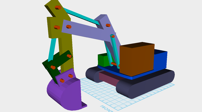
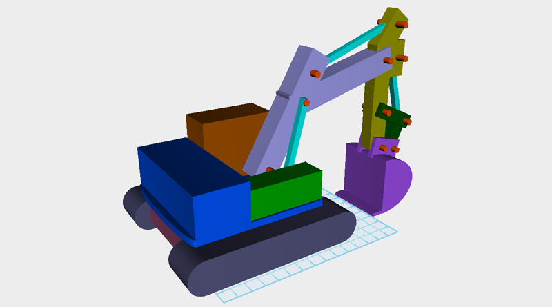
This tutorial’s scope covers how to use XYZmaker to make an excavator, and use the modeling tools to create articulated parts. For example, after putting all the parts together you will have made an excavator that will be able to move its scoop and arm. Because XYZmaker is targeted towards beginner modelers, we can only use the modeling features to create a basic structure, adjust the proportions according to your preferences, to create a unique 3D model.

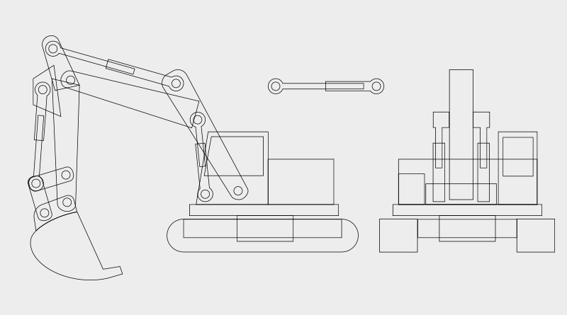
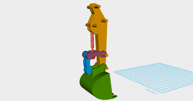
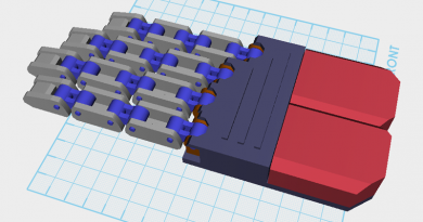
The excavator individual part groups are a little complicated, because of this, the model has been divided into various parts. These are: body, track, Chassis, boom, digging arm, bucket and other blocks. Individually create the parts and save them, then lastly take all the parts and combine them together, to finish a complete excavator 3D model. After collecting all of the reference material , hand draw or use graphic software to draw the outline of the excavator. During this stage you will be able to understand what parts need to move, or need hydraulic pistons, and count out all of the components. You don’t really need to focus too much on the dimensions and ratio or an actual excavator, because when you’re modeling you can constantly change the ratio and dimension of the parts.

In XYZmaker use basic geometric shapes to create a draft, by going through the modeling process you will also set every part’s dimension. Next, starting with the track, step by step model the excavator.
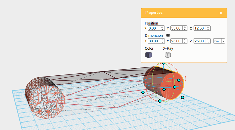
The track’s basic structure is a rectangle and two cylinders grouped together, for this create two cylinders and cube. Click on the rear cylinder and adjust its dimensions to X: 30,Y: 25,Z: 25 mm and position to X: 0,Y: 55,Z: 12.5.
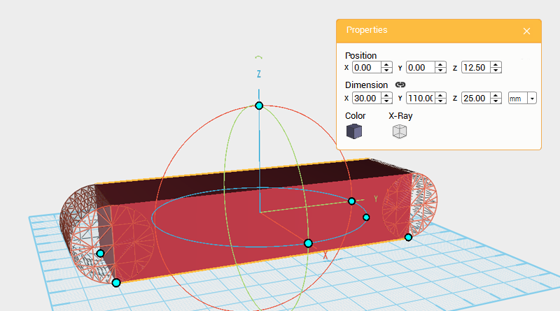
Change the cube’s dimensions to X: 30,Y: 110,Z: 25 mm and position to X: 0,Y: 0,Z: 12.5.
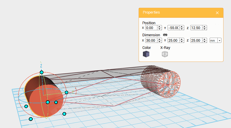
Select the front cylinder and change its dimensions to X: 30,Y: 25,Z: 25 mm and position to X: 0,Y: -55,Z: 12.5.
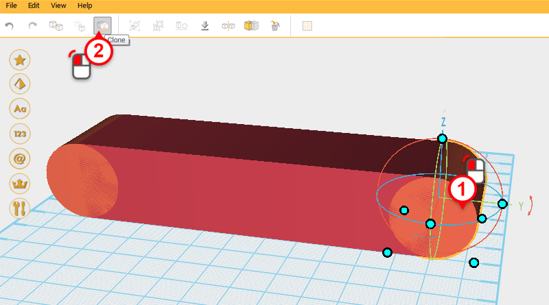
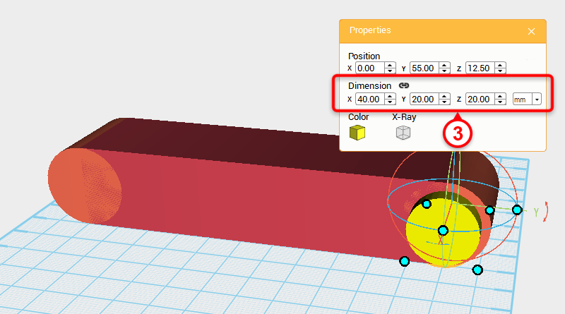
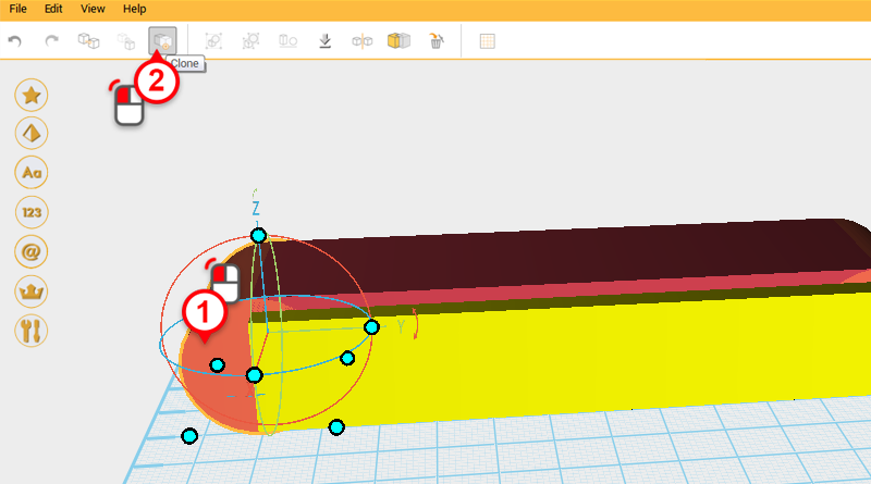
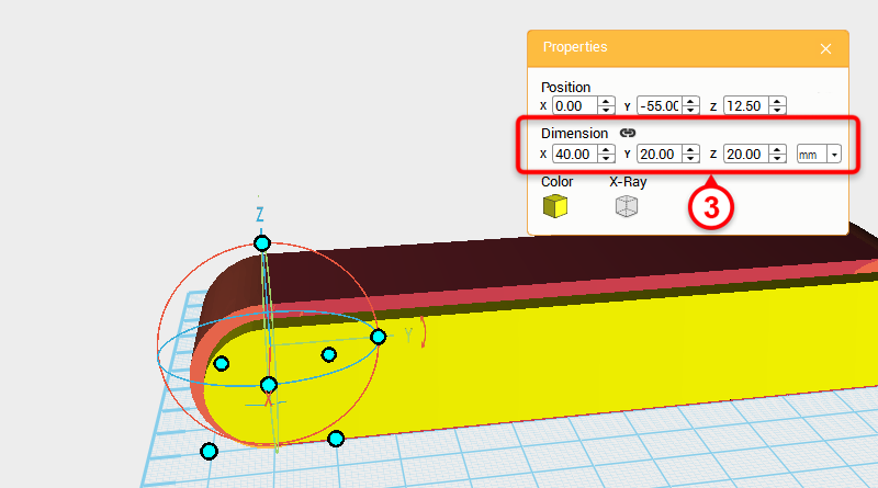
Next you want to cut a hole in the track, select one of the cylinders and click on the Clone button, in the Properties window change the dimensions to X: 40,Y: 20,Z: 20 mm.
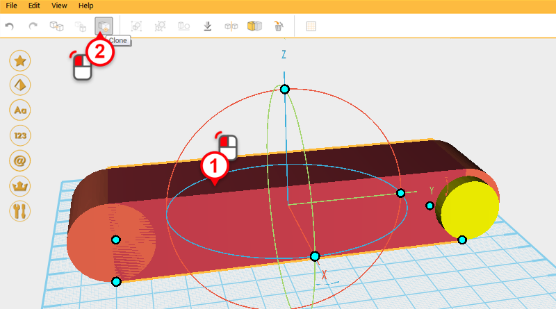
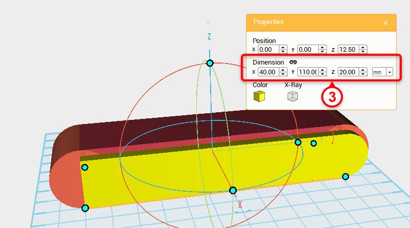
Select the Cube and click on the Clone button, in the Properties window change the dimensions to X: 40,Y: 110,Z: 20 mm.
Select the other Cylinder and click on the Clone button, in the Properties window change the dimensions to X: 40,Y: 20,Z: 20 mm.
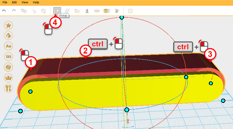
Select all 3 of the original parts you created and click on the Group button, this part will be called the track frame.
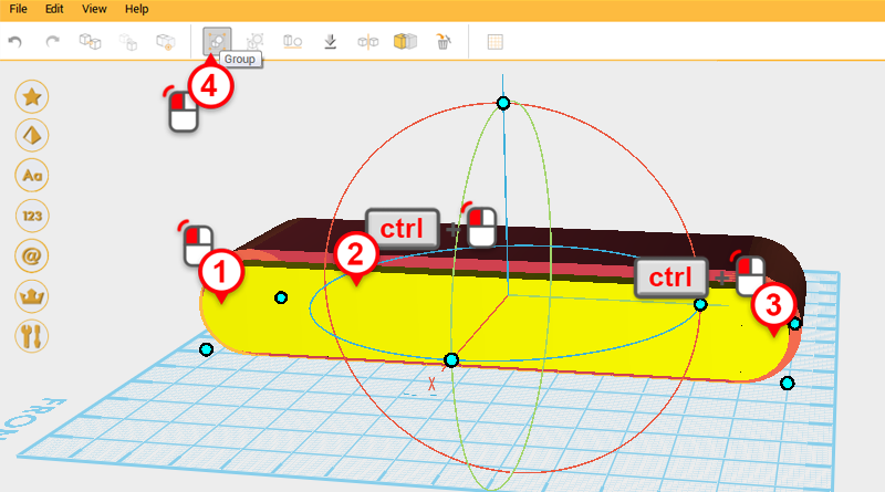
Select all three of the cloned parts and click on the Group button. This will be called the cutting part.
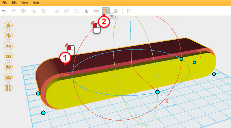
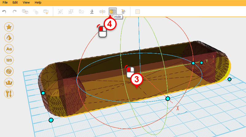
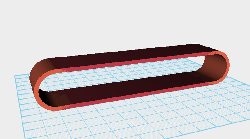
Select the track frame and click on the Hole button, next select the cutting part and click on the Hole button again to cut a hole in the middle of the track frame.
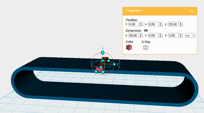
Next to detail the track guide, create a cube and in the Properties window, change the dimensions to X: 30,Y: 5,Z: 3 mm and position to X: 0,Y: 0,Z: 25.
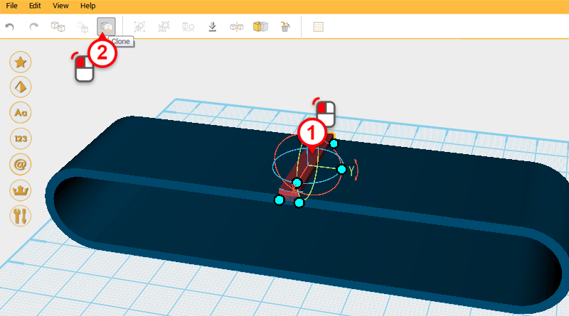
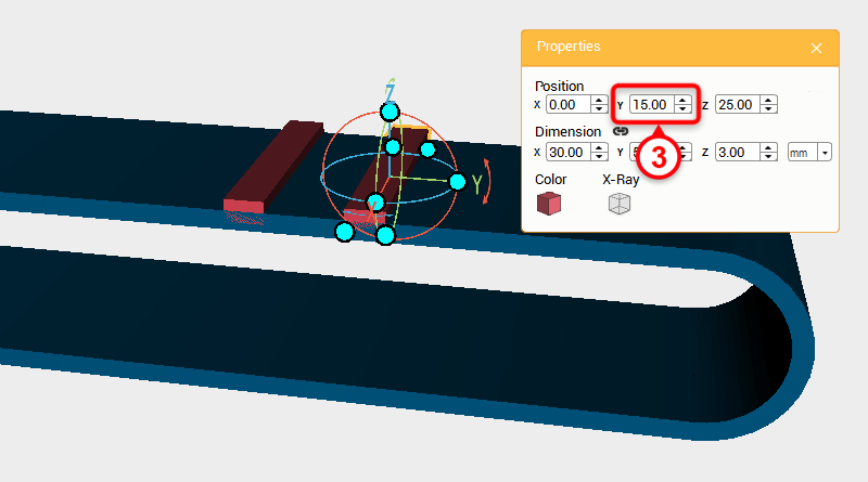
Select the cube and click on the Clone button. Then change the new part’s Y axis position to 15.
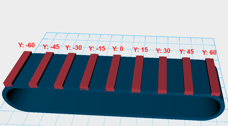
Continue copying the cube part and changing the part’s Y axis position as shown in the image above, until all of the cubes will evenly spaced by 15mm along the Y axis.
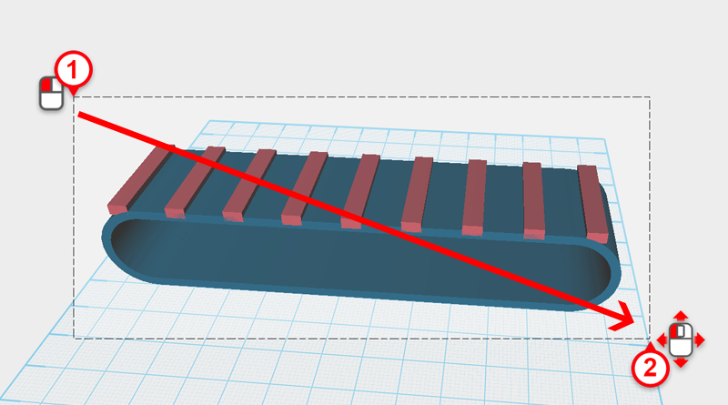
Drag select all of the parts.
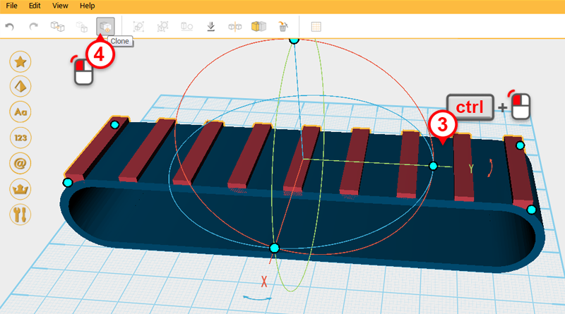
Press and hold the ctrl key and click on the track frame again to deselect it. Next click on the Clone button.
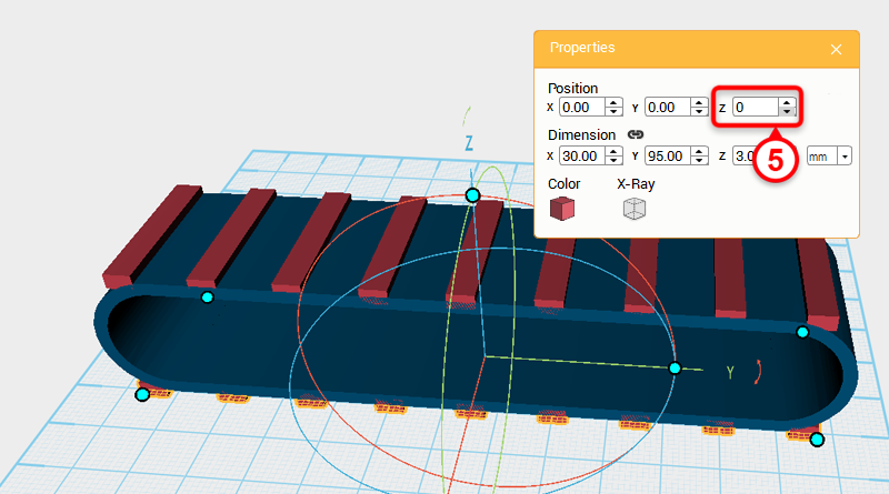
When you do this all of cubes will be copied in the same place. Next in the Properties window change the new part’s Z axis position to 0.
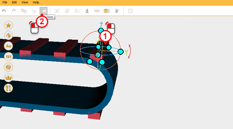
The track tread on the top and bottom is already finished, now all that is left is the tread on both ends. In the bottom left hand corner of the screen click on the modeling grid button to turn off the grid so that you can better see the model. Select one of the cubes and click on the Clone button to copy it.
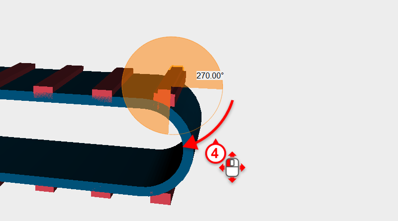
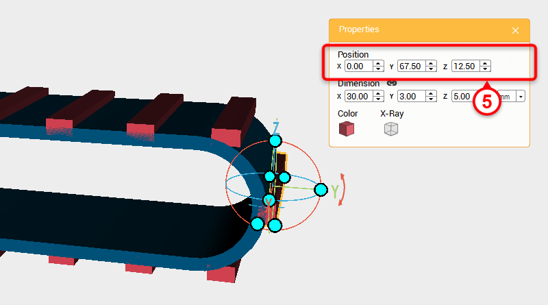
Rotate the part 270° along the X axis then change its position to X: 0,Y: 67.5,Z: 12.5.
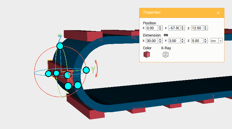
As shown in the image above, click on the other end of the track and do the same.
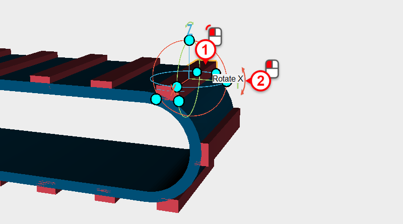
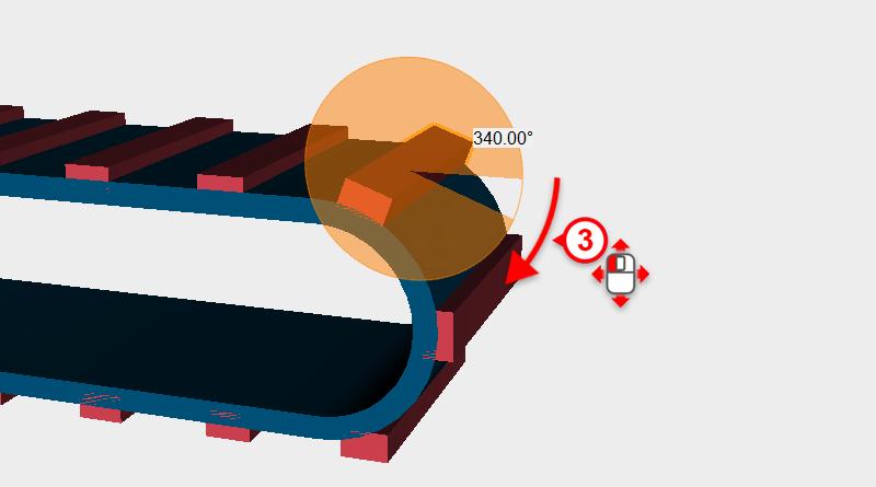
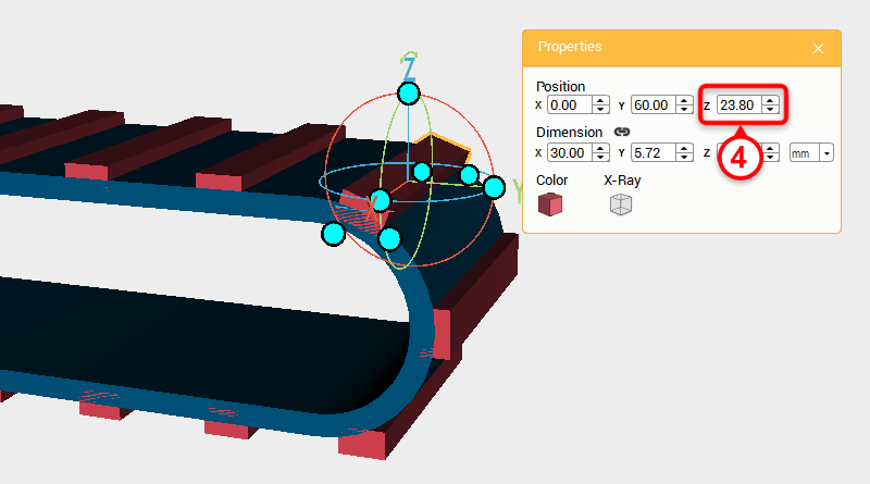
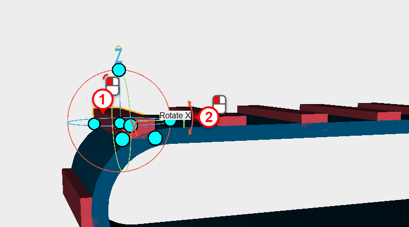
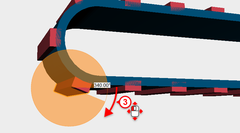
The tread where the track bends needs to be adjusted, because of this select the cube in the image above, then rotate it along the X axis 340 degrees, and adjust the Z axis position to 23.8
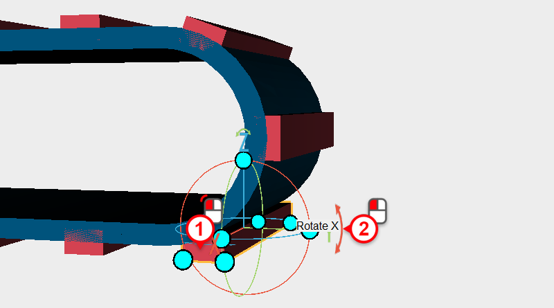
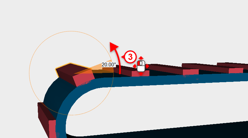
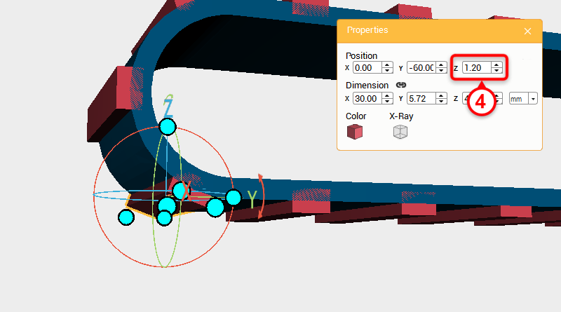
The same as before, select the cube shown in the image above and rotate it 20 degrees along the X axis, then adjust the X axis position to 1.2.
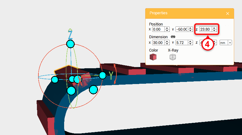
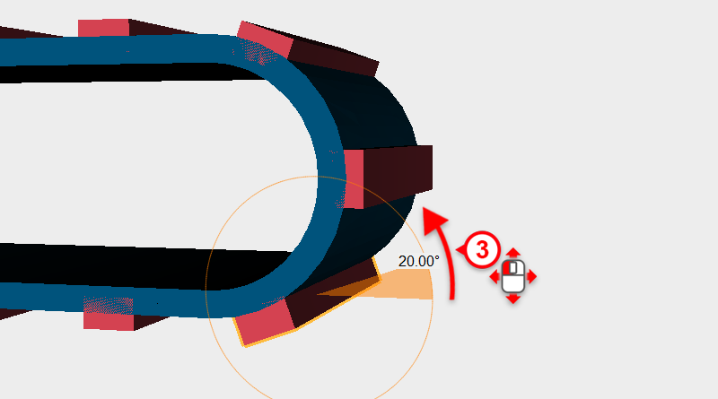
Select the cube in the image above and rotate it 20 degrees along the X axis, then adjust the Z axis position to 23.8.
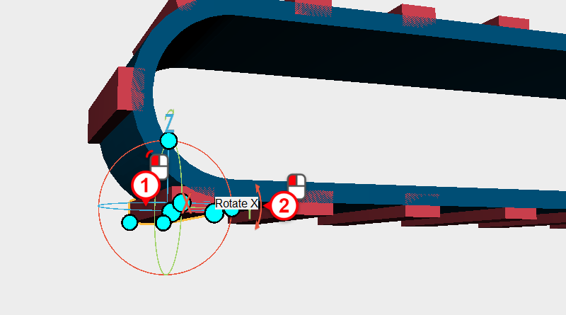
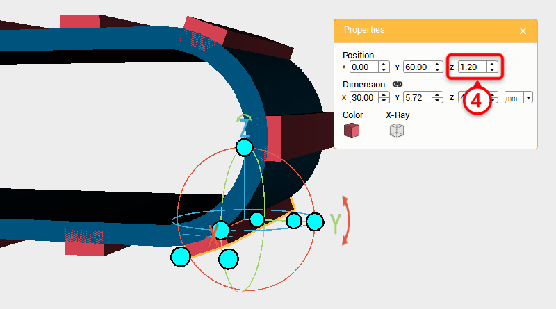
Select the cube as shown in the image above and rotate it along the X axis by 340°, then change its Z axis position to 1.2.
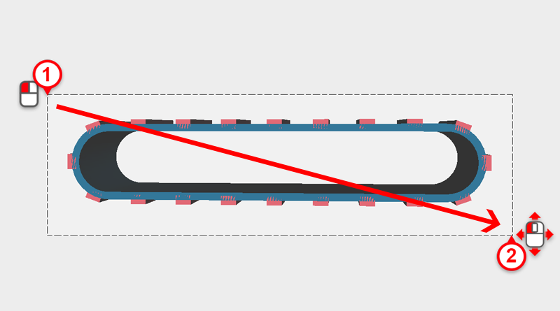
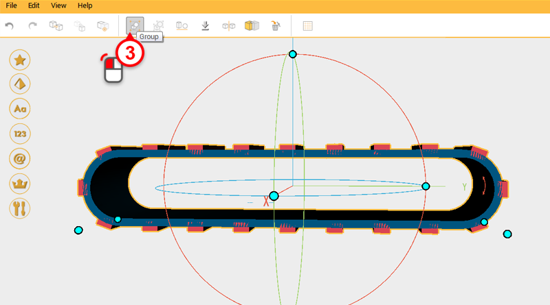
Drag select all the parts and click on the Group button. The track frame is complete.
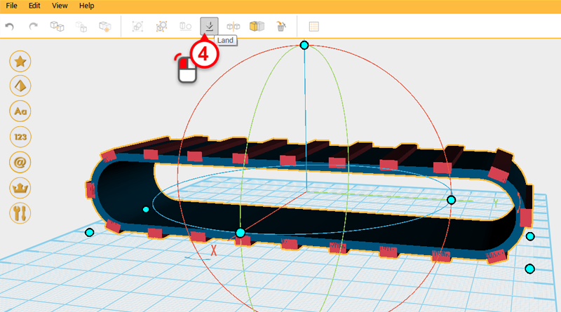
Next click on the Land button to sit the track frame on the modeling grid.