XYZmaker tutorial – Robot Hand part 1

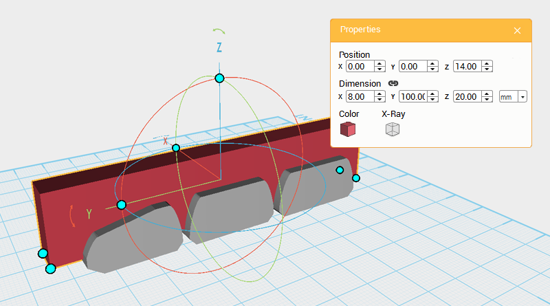
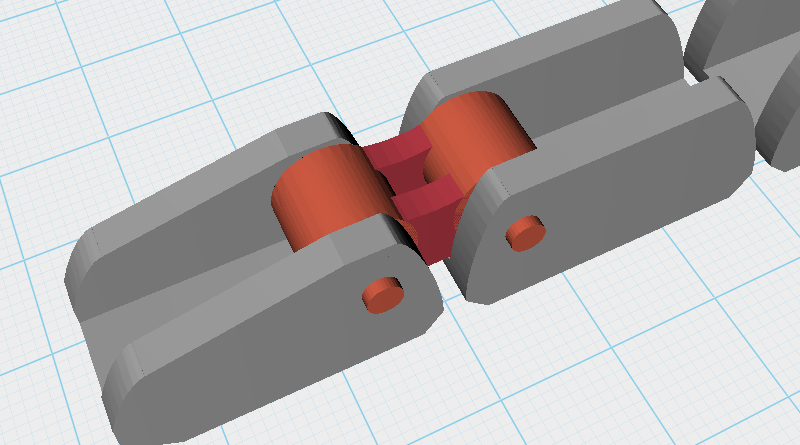
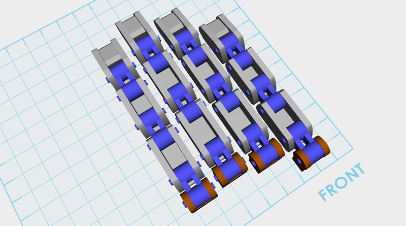
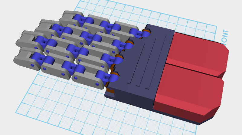
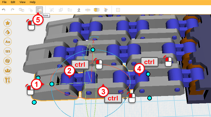
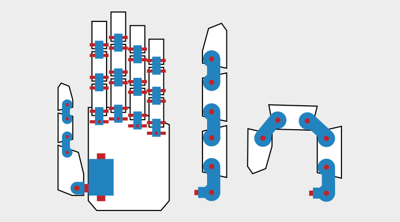
This tutorial uses XYZmaker to model basic 3D shapes, combine, and edit them – teaching you to create a functioning model of a robotic hand that is able to close and open. First collect some reference material and compare all the different types of robotic hands.   Next,  using paper or sketching software, plan all the parts that you need to make and their individual rotation joints. After creating this reference drawing, use a chain-like structure for the joints, and give the finger links a bigger range of mobility. The blue parts in the image above are the joints, and the red parts will act as shafts that hold the pieces together.   Create a cube and change its dimensions to X: 14,Y: 28,Z: 14 mm and position to X: 0,Y: 0,Z: 7. Call this part the Finger joint A.   Select Finger joint A and click Clone. Next, change the dimensions to X: 20,Y: 10,Z: 30 mm, and position to X: 0,Y: -18,Z:

Read more

XYZmaker tutorial – Robot Hand part 2

Next cut out the shape of the front end of the fingertip, create a Cube and change its dimensions to X: 20,Y: 30,Z: 10 mm and position to X: -28,Y: 5.5,Z: 17. Call this Cutting part.   Select the Cutting part, click and drag on the rotation arrow next to the Y-axis, rotating the part 350°.   Next, use the Cutting part and the Hole function to cut the top of the fingertip as shown in the image above.   Create a Cylinder and rotate it 90° along the Y-axis, then change its dimensions to X: 14,Y: 4,Z: 12 mm and position to X: -28,Y: 18,Z: 5.3.   Select the Cylinder, click and hold the arrow next to the Y-axis in the bounding box, then drag the part, rotating it 25°.   Next change its Y-axis position to 14.   Select the Cylinder, then press and hold ctrl and click on the Fingertip to select the two parts. Next, click on Group to group them.   Create a Cube and rotate it 30° along

Read more

XYZmaker tutorial – Robot Hand part 3

Create a Cylinder and rotate it 90° along the Y-axis, then change its dimensions to X: 16,Y: 3,Z: 3 mm and position to X: 0,Y: 9,Z: 9. This will be used as a rotation anchor point.   Select the Cylinder you just created and click on Clone to duplicate another Cylinder. Change this new part’s dimensions to X: 8,Y: 9,Z: 9 mm.   Select the two Cylinders shown in the image above, click Clone, and change the parts Y-axis position to 21.   Create a Cube and change its dimensions to X: 8,Y: 12,Z: 10 mm, and position to X: 0,Y: 15,Z: 9.5.   Create a Cylinder and rotate it 90° along the Y-axis, change its dimensions to X: 20,Y: 23,Z: 25 mm, and position to X: 0,Y: 15,Z: 24.   Select the Cube and click on Hole.   Select the Cylinder and click Hole again.   Create a Cube and change its dimensions and position as shown in the image above. Call this the Cutting part.   Next use the Cutting part and Hole

Read more

XYZmaker tutorial – Robot Hand part 4

Drag select all the parts and click Clone. Change the X-axis position of the cloned finger to 18. Call this the Middle finger.   Because the Middle finger needs to be longer than the Index finger, elongate the new part.  Change the Y-axis dimensions of the fingertip and finger links to the dimensions shown above.   After arranging the dimensions, change the Y-axis position of the three parts as shown above to keep the spacing consistent.   Lastly, adjust the Knuckles’s Y-axis as shown above.   As above, drag select the Index finger parts and click Clone.  Next, change the part’s X-axis position to 36. This new part is the Ring finger, because it is the same length as the Index finger, its length doesn’t need to be adjusted. Tip: If you accidentally drag selected the wrong part, hold down ctrl and click on that part to deselect it.   Drag select the Ring finger, click Clone, and change the part’s X-axis position to 54.

Read more

XYZmaker tutorial – Robot Hand part 5

Next, start making the palm, drag select all the finger parts and change their position to:X: 0,Y: 45,Z: 11.   Create a Cube and change its dimensions to X: 75,Y: 81,Z: 5 mm and position to X: 0,Y: -46,Z: 2.5.   Create another Cube and change its dimensions to X: 18.5,Y: 12,Z: 5 mm and position to X: 9,Y: -0.5,Z: 2.5. This will extend the palm area to connect with the Ring finger.   Create a Cube and change its dimensions to X: 18.5,Y: 16,Z: 5 mm and position to X: -9,Y: 1.5,Z: 2.5. This will extend the palm area to connect with the Middle finger.   Create a Cube and change its dimensions to X: 20,Y: 14,Z: 5 mm and position to X: -27.5,Y: 0.5,Z: 2.5. This will extend the palm area to connect with the Index finger.   Change viewing angle so that you are viewing the parts from above. Select all the Palm parts as shown in the image above and click Group to finish the Palm plane.   Create a Cube

Read more

XYZmaker tutorial – Robot Hand part 6

Next start creating the Thumb, for this use the Fingers and Knuckles produced earlier to create this part, but because the base of the thumb is a little different from the other fingers, you will need to produce a new one. Create a Cube and change its dimensions to X: 14,Y: 46,Z: 22 mm, and position to X: -70,Y: -50,Z: 11. Call this part the Thumb base.   Select the Thumb base and click Clone. Next change the part’s dimensions to X: 18,Y: 10,Z: 40 mm and position to X: -70,Y: -24,Z: 11. Call this part the Cutting part.   Select the Cutting part, click and hold the arrow next to the Y-axis line and drag it, rotating the part 25°.   Select the Cutting part and click Clone. Next, change the Y-axis position to -78.   Use the two Cutting parts and the Hole function to cut away from the Thumb base as shown above.   Create a Cube and change its dimensions to X: 20,Y:

Read more

XYZmaker tutorial – Robot Hand part 7

Next, create the joint that connects the Thumb and Palm. Create a Cylinder and rotate it 90° along the Y-axis then change the part’s dimensions to X: 16,Y: 5,Z: 5 mm and position to X: -70,Y: -65,Z: 16. Select the Cylinder and click Clone. Change the new part’s dimensions to X: 8,Y: 14,Z: 14 mm.   Create a Cube and change its dimensions to X: 8,Y: 14,Z: 8 mm and position to X: -70,Y: -65,Z: 20.   Next, take the Thumb and make it thicker; drag select the parts as shown above, then change their X-axis dimension to 20mm.   Select the Cylinder in the image above and click Clone. With the new part, click and drag the arrow next to the Z-axis in the bounding box of the new part, and rotate the part 90°.   Lastly, take the Cylinder and change its dimensions to X: 8,Y: 8,Z: 10 mm and Z-axis position to 26.   Drag select the parts shown in the image above, then while holding down

Read more

XYZmaker tutorial – Robot Hand part 8

Next create a cover for the back of the hand. First, hide the work plane grid to make viewing the model easier. Create a Cube and change its dimensions to X: 82,Y: 110,Z: 32 mm and position to X: 0,Y: -36,Z: 7. Call this part the Back hand cover.   To accommodate the Palm center’s shape, cut away material from the Back hand cover. Create a Cube and place it beside the Back hand cover, then rotate the part 45° along the Z-axis. Call this the Cutting part.   Change the Cutting part’s Z-axis dimension to 40mm and position to X: -42,Y: -92,Z: 7.   Select the Cutting part and click Clone; change the new part’s X-axis dimension to 42.   Use the two Cutting parts and the Hole function to cut away material from the Back hand cover.   Select the Back hand cover and click Clone. Next, change the part’s dimensions to X: 76,Y: 104,Z: 32 mm, and Z-axis position to 16.

Read more

XYZmaker tutorial – the Excavator part 1

This tutorial’s scope covers how to use XYZmaker to make an excavator, and use the modeling tools to create articulated parts. For example, after putting all the parts together you will have made an excavator that will be able to move its scoop and arm. Because XYZmaker is targeted towards beginner modelers, we can only use the modeling features to create a basic structure, adjust the proportions according to your preferences, to create a unique 3D model. The excavator individual part groups are a little complicated, because of this, the model has been divided into various parts. These are: body, track, Chassis, boom, digging arm, bucket and other blocks. Individually create the parts and save them, then lastly take all the parts and combine them together, to finish a complete excavator 3D model. After collecting all of the reference material , hand draw or use graphic software to draw the outline

Read more

XYZmaker tutorial – the Excavator part 2

After completing the track frame, continue to make the internal structure of the track. Create a cylinder and rotate it 90 ° along the Y axis, then change the dimensions to X: 25,Y: 20,Z: 20 mm and position to X: 0,Y: -55,Z: 14.   Clone the cylinder and change its dimensions to X: 25,Y: 18,Z: 18 mm and position to X: 22,Y: -55,Z: 14. Call this part the cutting part.   Use the cutting part and the Hole function to cut a recess into the cylinder.   Create a sphere and adjust its dimensions to X: 6,Y: 15,Z: 15 mm and position to X: 9,Y: -55,Z: 14.   Select the cylinder and sphere and click in the Group button, to finish the big wheel.   Clone the big wheel and change its Y axis position to 55.   Create a cylinder and rotate it 90° along the Y axis, change the dimensions to X: 20,Y: 8,Z: 8 mm and position to X:

Read more