XYZmaker tutorial – the Excavator part 2
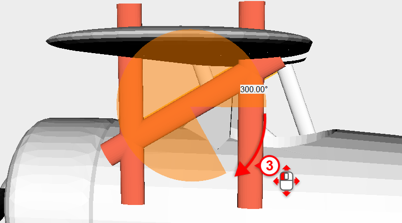
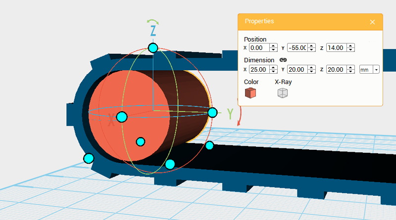 After completing the track frame, continue to make the internal structure of the track. Create a cylinder and rotate it 90 ° along the Y axis, then change the dimensions to X: 25,Y: 20,Z: 20 mm and position to X: 0,Y: -55,Z: 14.
 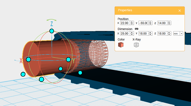 Clone the cylinder and change its dimensions to X: 25,Y: 18,Z: 18 mm and position to X: 22,Y: -55,Z: 14. Call this part the cutting part.
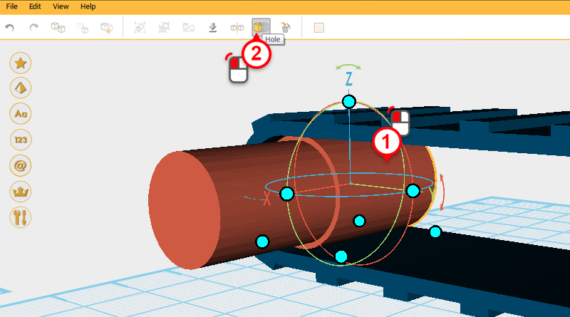
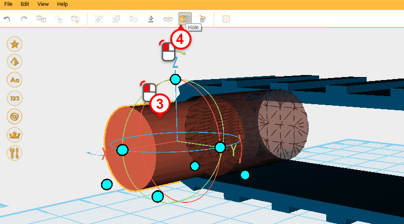
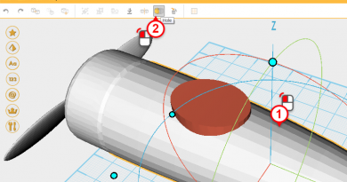
 Use the cutting part and the Hole function to cut a recess into the cylinder.
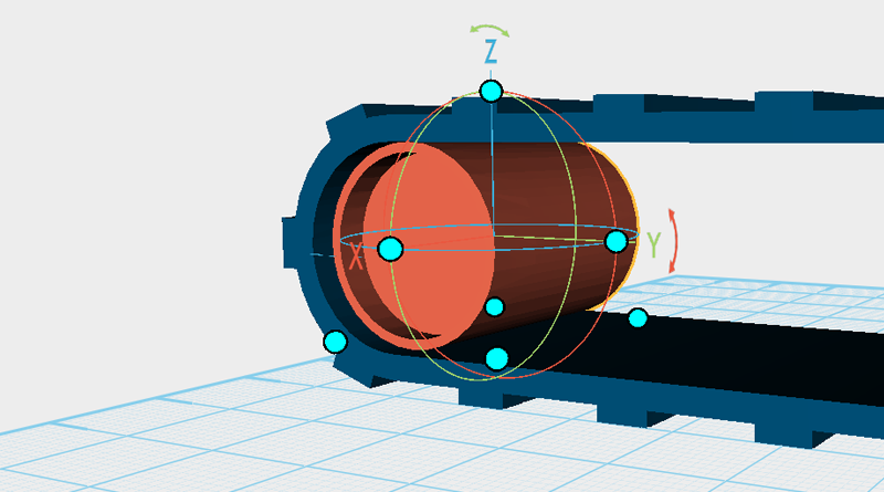
 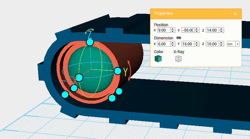 Create a sphere and adjust its dimensions to X: 6,Y: 15,Z: 15 mm and position to X: 9,Y: -55,Z: 14.
 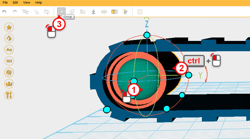 Select the cylinder and sphere and click in the Group button, to finish the big wheel.
 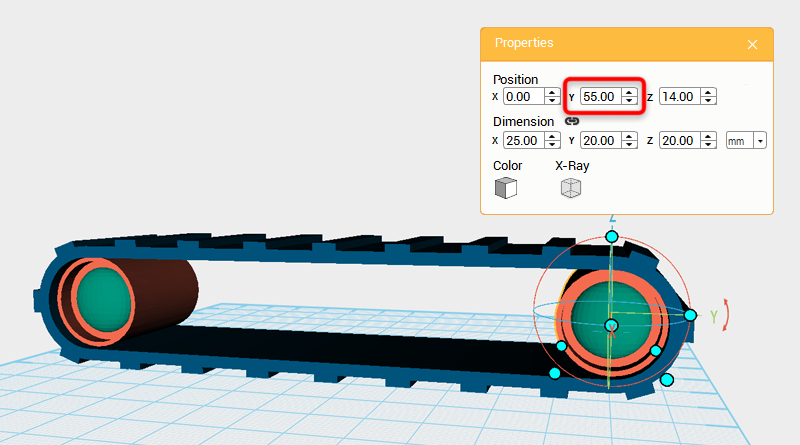 Clone the big wheel and change its Y axis position to 55.
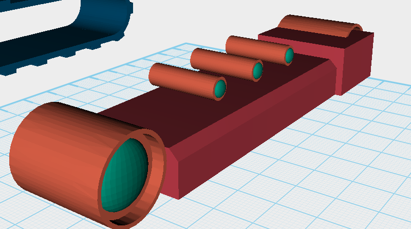
 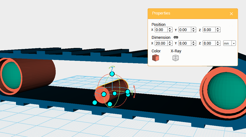 Create a cylinder and rotate it 90° along the Y axis, change the dimensions to X: 20,Y: 8,Z: 8 mm and position to X: 0,Y: 0,Z: 8.
 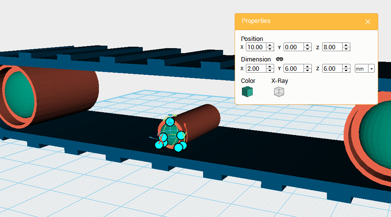 Create a sphere and change its dimensions to X: 2,Y: 6,Z: 6 mm and position to X: 10,Y: 0,Z: 8.
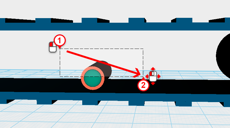
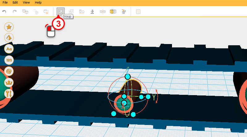 Drag select the cylinder and sphere you just created and click on the Group button. This part will be called the lower small wheel.
 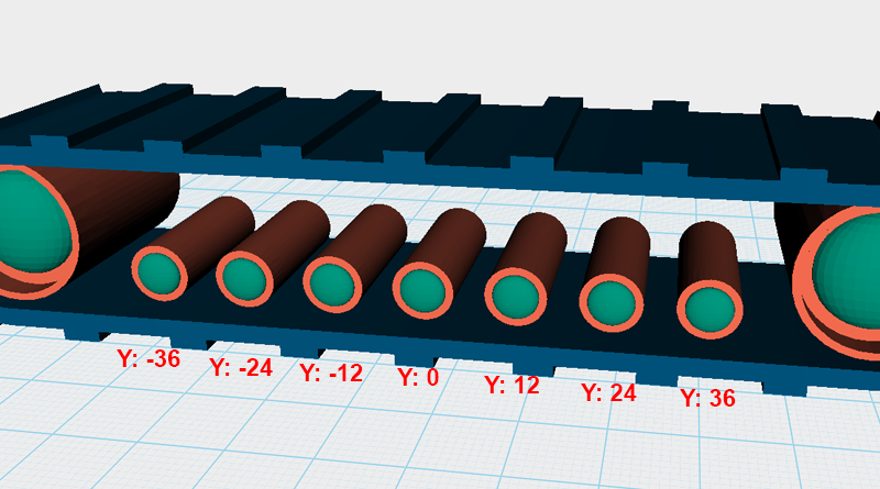 Clone the lower small wheel 7 times, each time adjusting its Y axis value as shown in the image above to create 7 parts equally spaced 12mm apart.
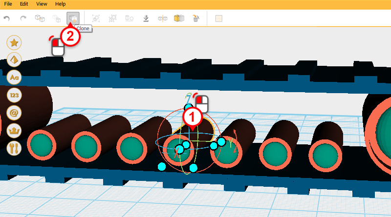
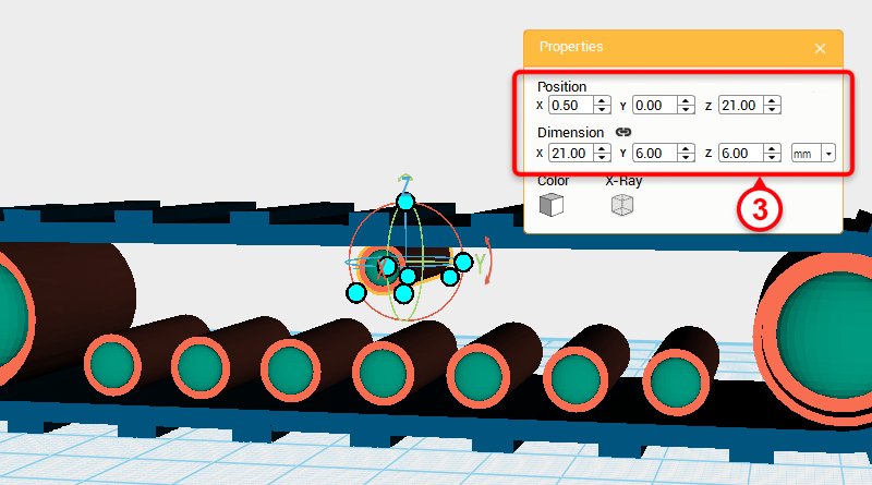 Select the lower small wheel in the center and click on the Clone button, then change its dimensions to X: 21,Y: 6,Z: 6 mm and position to X: 0.5,Y: 0,Z: 21. This part will be called the upper small wheel.
 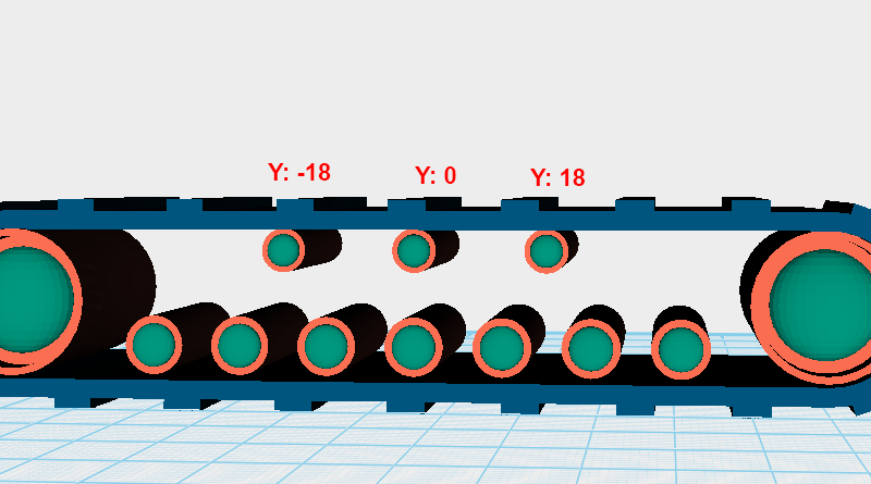 Click on the upper small wheel and clone it two times. Change its Y axis position to the dimensions shown in the image above, so that all the upper small wheels at spaced evenly 18mm apart.
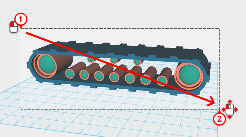
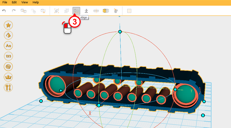
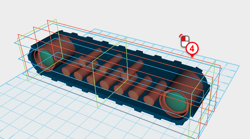 Drag select all the parts and click on the Align button, then click on the furthest red frame shown in the image above to align all the parts.
Tip: To align all the parts flat for printing, use the bottom box.
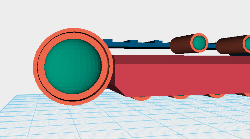
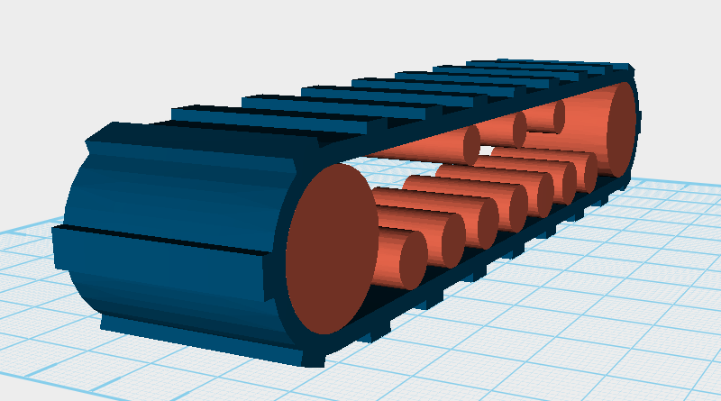 After aligning everything the part should look as above.
 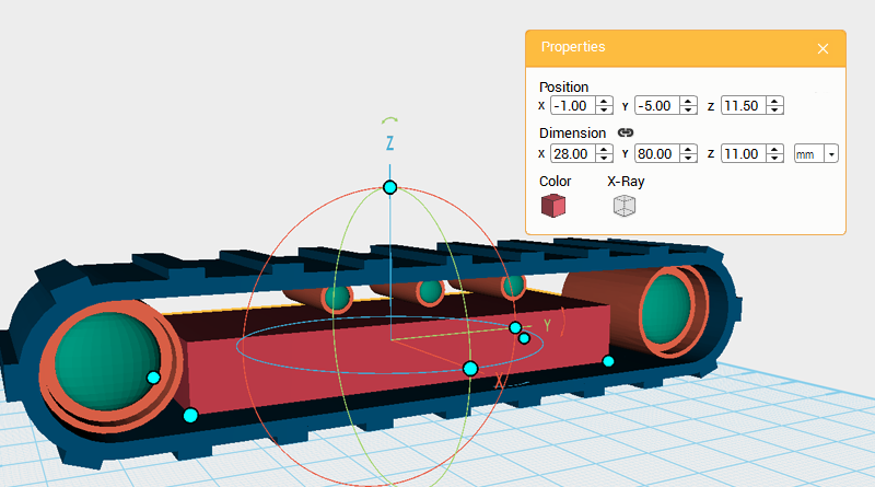 Next you want to create the track motor structure, create a cube and change its dimensions to X: 28,Y: 80,Z: 11 mm and position to X: -1,Y: -5,Z: 11.5。
 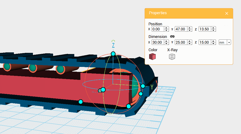 Make another cube and change its dimensions to X: 30,Y: 25,Z: 15 mm, then change its position to X: 0,Y: 47,Z: 13.5.
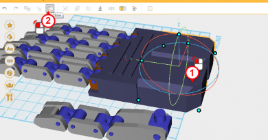
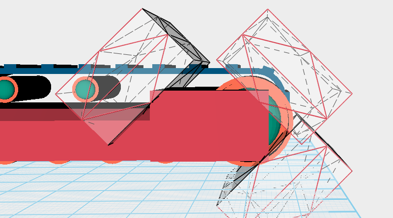
 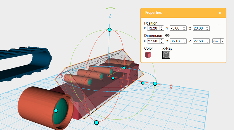 First take the track frame and slide it along the X axis so that it’s easier to model the other components. Clone the larger of the two cubes and rotate it 45° along the Y axis, then enlarge its Y axis dimension slightly, and move it as shown in the image above. This part will be called the cutting part.
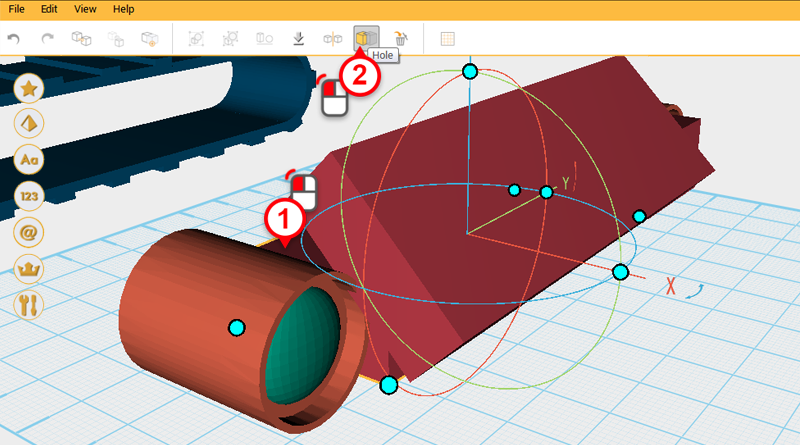
 Use the cutting part and the Hole function to cut a chamfer into the larger cube.
Tip: If you're unable to get the cut you want, use the undo tool to change it back to its original shape, then use move the cutting part's position slightly and try again.
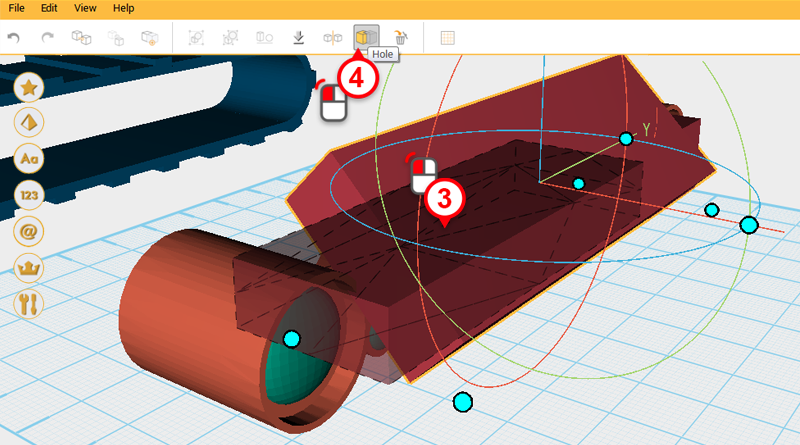
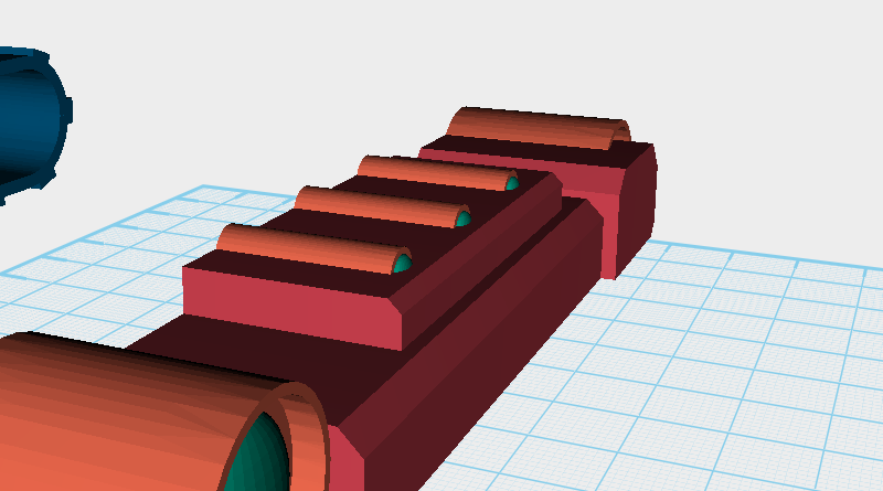
 After cutting the part should look like this.
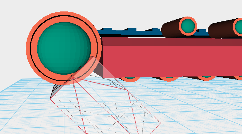
 Repeat the same method to create more chamfers on both cubes.
 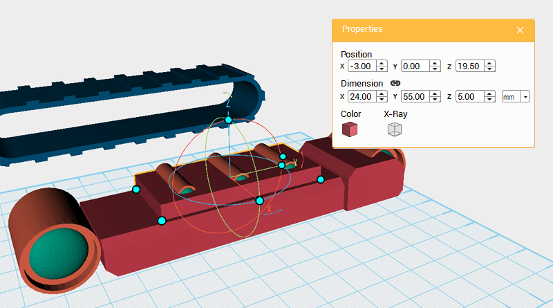 Continue to add more to the track frame structure, create a cube and change its dimensions to X: 24,Y: 55,Z: 5 mm and position to X: -3,Y: 0,Z: 19.5.
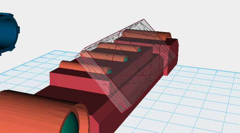
 The same as before, clone the cube and use it to chamfer the original cube’s edges. After adjusting the cloned parts dimensions, angle, and position, use the Hole function to cut away the edge and leave a chamfer.
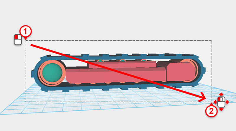
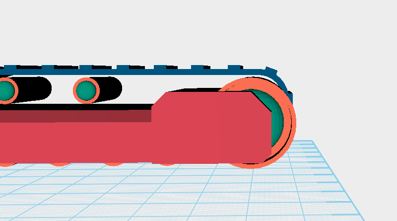
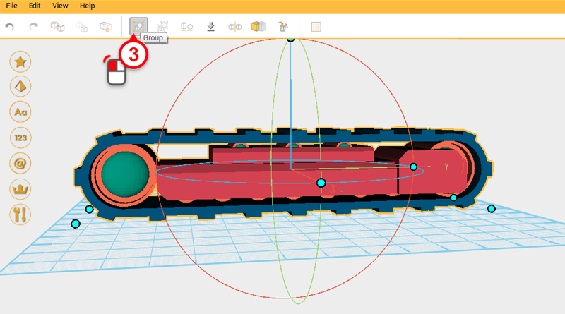 Take the track frame and move it back to its original position of X: 0,Y: 0,Z: 14. Drag select all of the parts and click on the Group button. This finishes the right-hand track assembly.
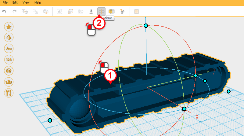
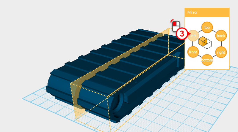 Select the right-hand track assembly and click on the mirror button, in the Mirror Properties window click on the left button, this will reflect a left-hand track assembly.
 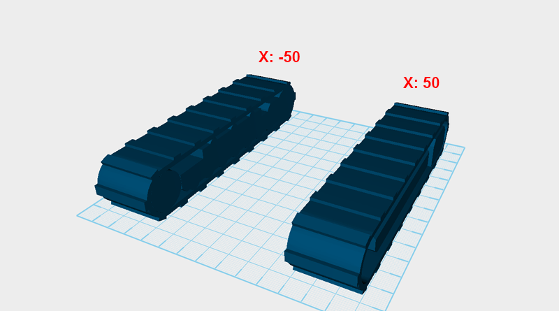 Take the left-hand track assembly and change its X axis position to -50, change the right-hand track assembly’s X axis position to 50.
 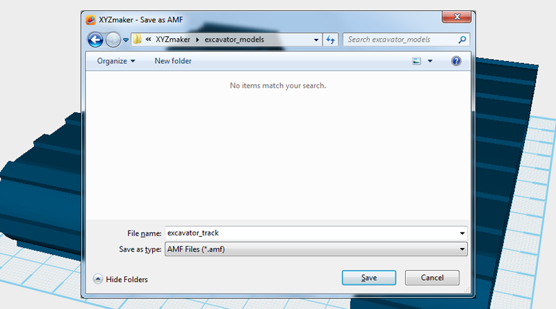 Save this part as 「excavator_track.amf」.