XYZmaker tutorial – the Excavator part 10
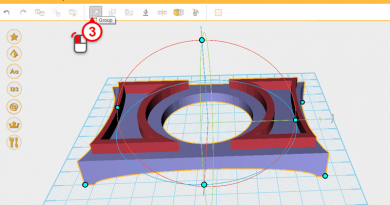
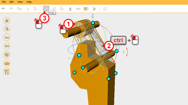 There are two hydraulic rods that separate the top of the digging arm from the bucket, because of this you need to cut away room for the hydraulic rods. First open the excavator_arm.amf file, select the two parts shown in the image above and press the Group button.
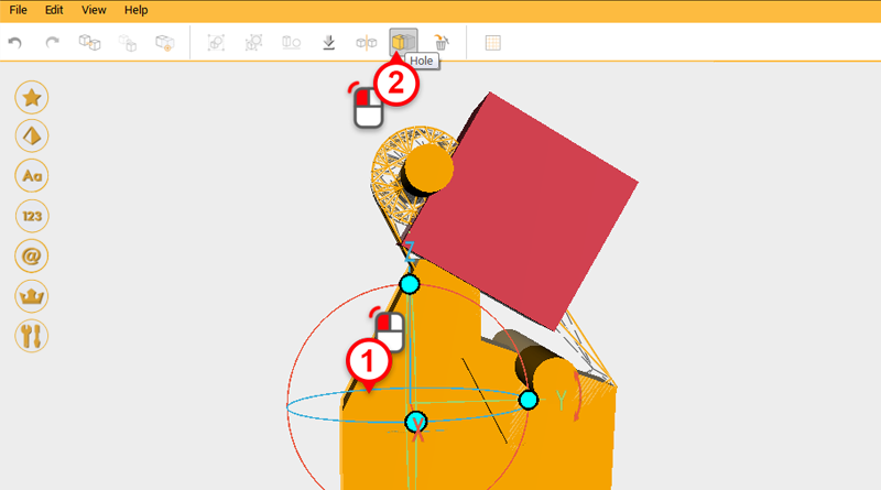
 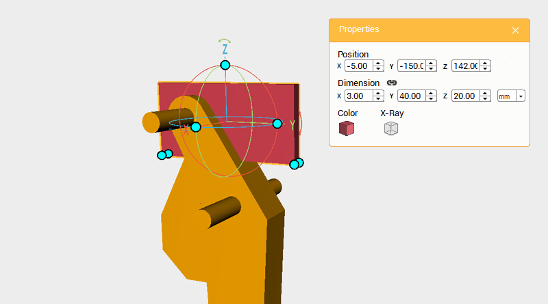 Create a cube and change its dimensions to X: 3,Y: 40,Z: 20 mm and position to X: -5,Y: -150,Z: 142. Call this part the cutting part.
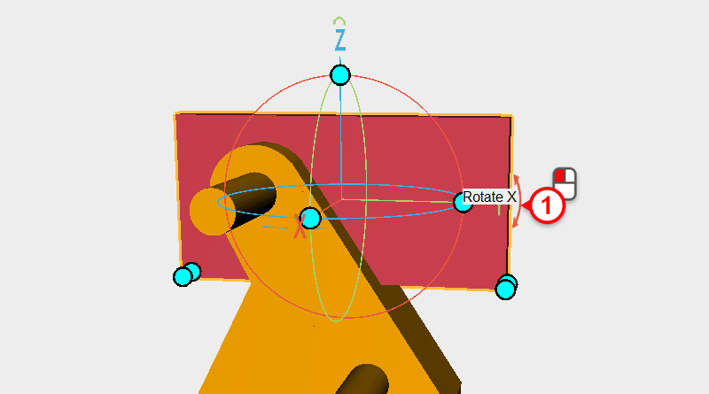
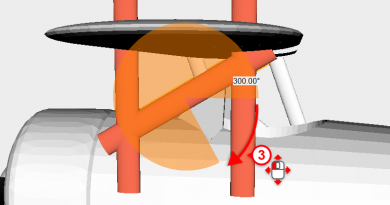
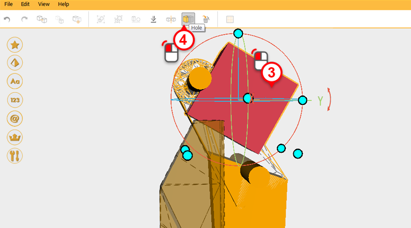
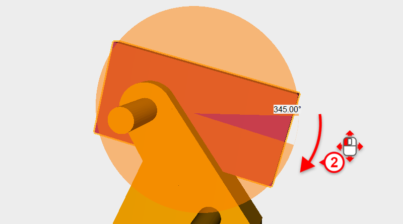 With the cutting part individually selected, click on the arrow next to the Y axis in the control orb, and drag the mouse down to rotate the part 345 degrees.
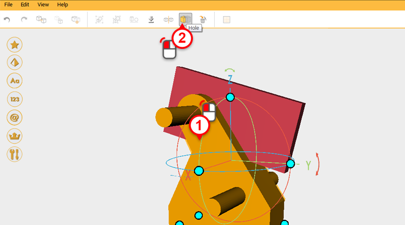
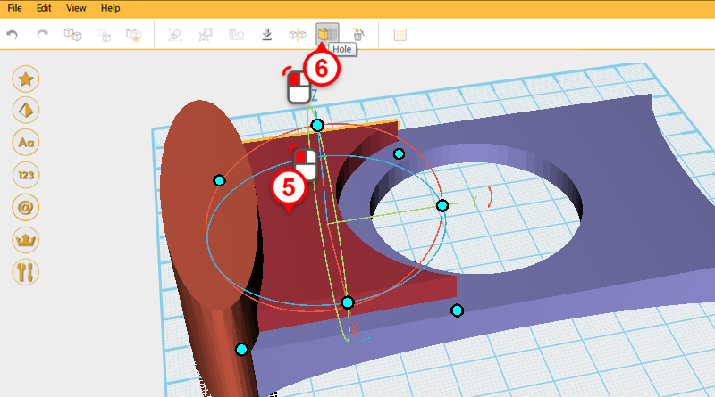
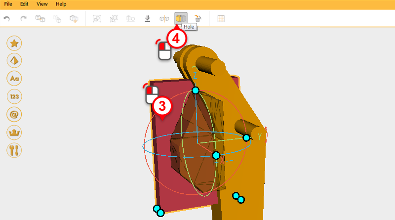
 Use the cutting part and the Hole function to cut a trench in the top of the digging arm. Refer to image above.
 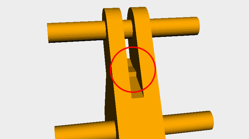 After cutting you might notice part of the model protruding inside the trench similar to the area outlined in the image above.
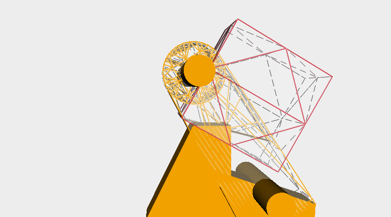
 Create another cube and use it to cut away the protruding part as above.
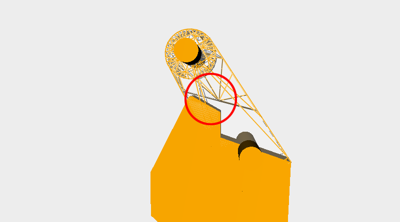
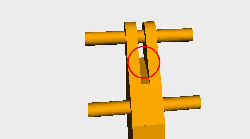 After cutting, the place where the protruding part was should be smooth (refer to the area in red).
 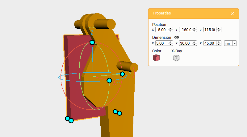 Create a cube and change the dimensions to X: 3,Y: 40,Z: 20 mm and position to X: -5,Y: -150,Z: 142. Use this part for cutting.
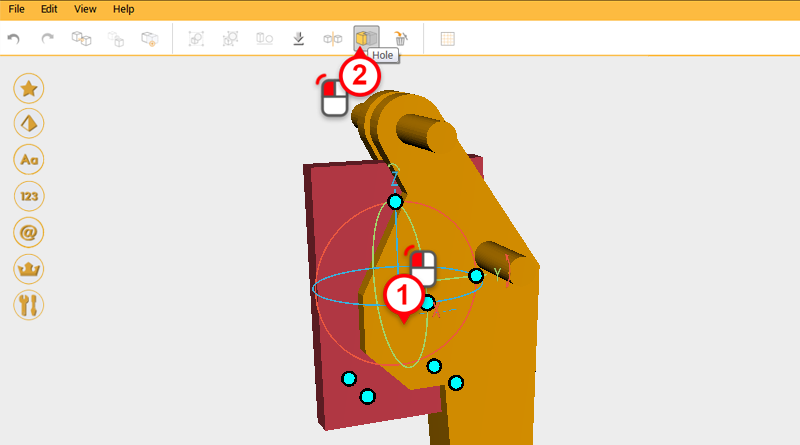
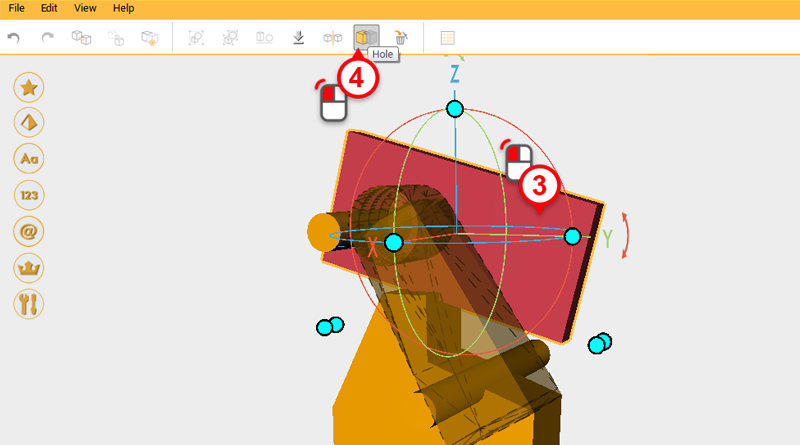
 Use the cutting part and the Hole function to cut away a trench in the front of the digging arm.
 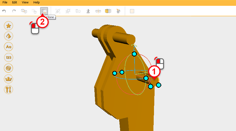 Select the cylinder shown above and click on the Clone button.
 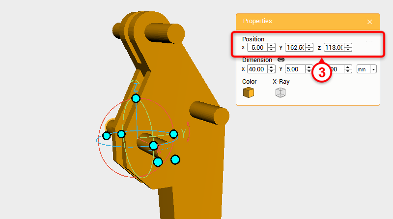 Change a position of the cloned part to X: -5,Y: -162.5,Z: 113.
 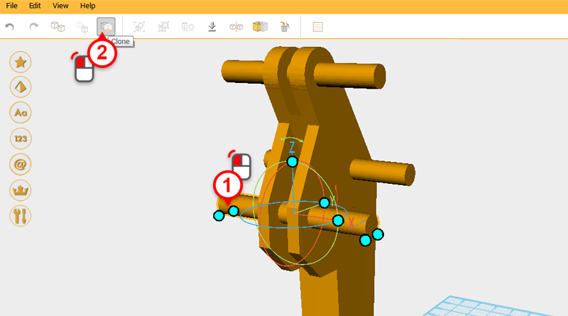 Select the cylinder you just cloned and click on the Clone button.
 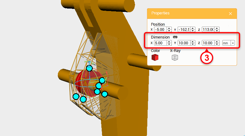 Change the dimensions to X: 5,Y: 10,Z: 10 mm and the part color to red so that it is easier to see the part.
 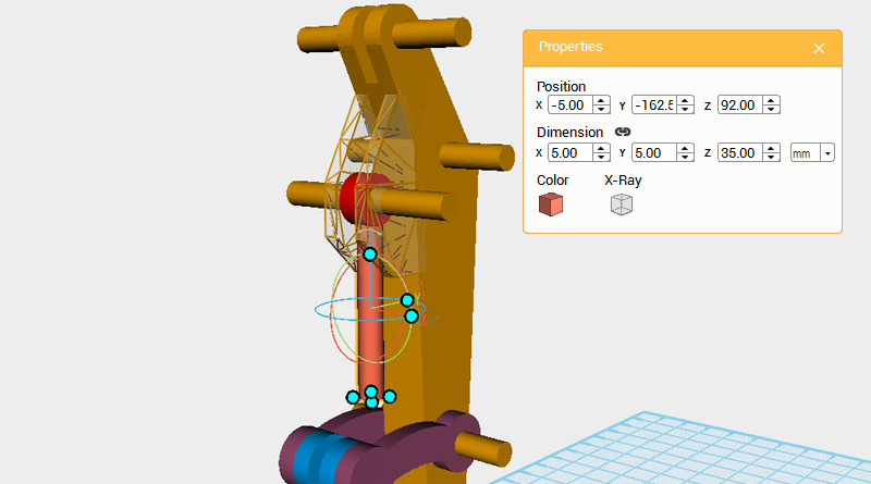 Create a cylinder and change its dimensions to X: 5,Y: 5,Z: 35 mm and position to X: -5,Y: -162.5,Z: 92.
 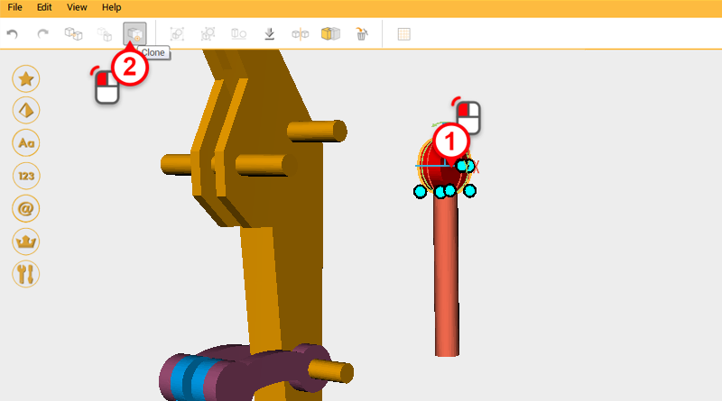 First take the two cylinders that you just created and move them to the side, then select the red cylinder and click on the Clone button.
 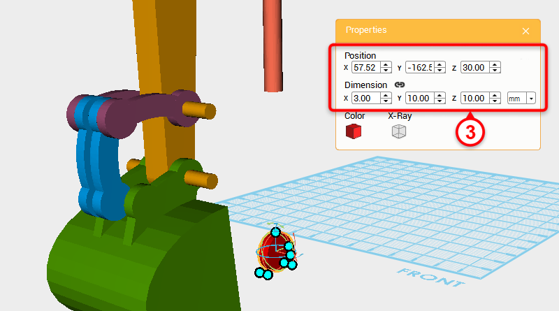 Change the cloned part’s X axis dimension to 3mm and Z axis position to 30.
 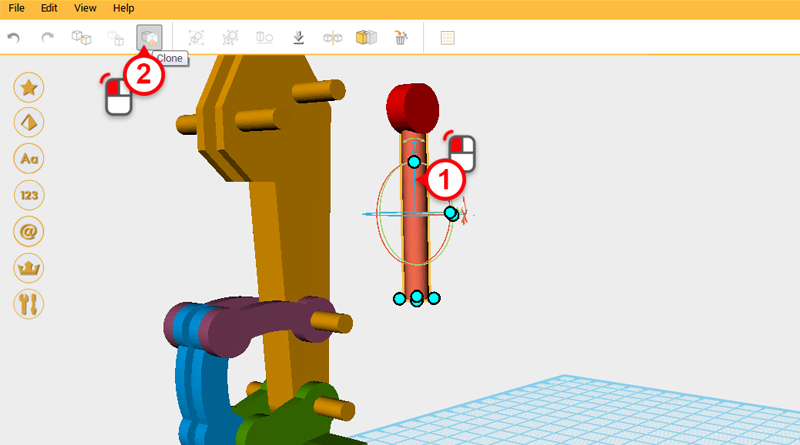 Select the orange cylinder and click on the Clone button.
 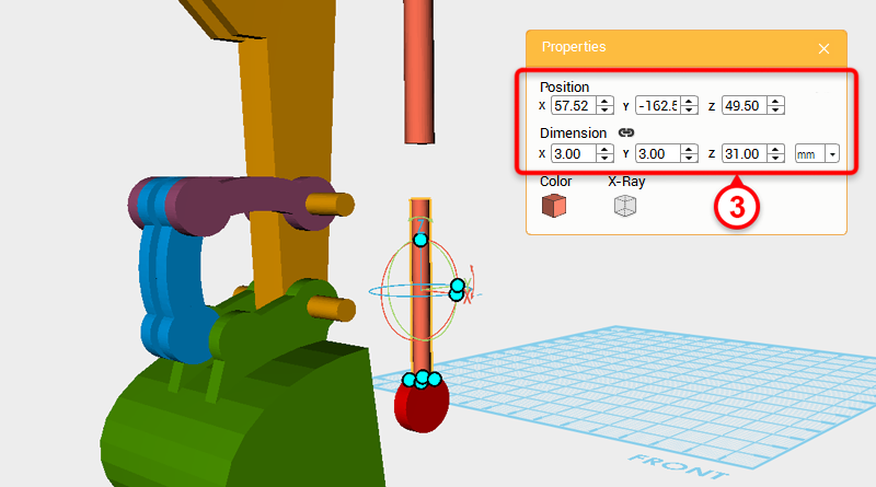 Change the cloned part’s X and Y axis dimension to 3mm, and Z axis position to 49.5.
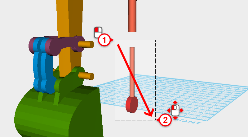
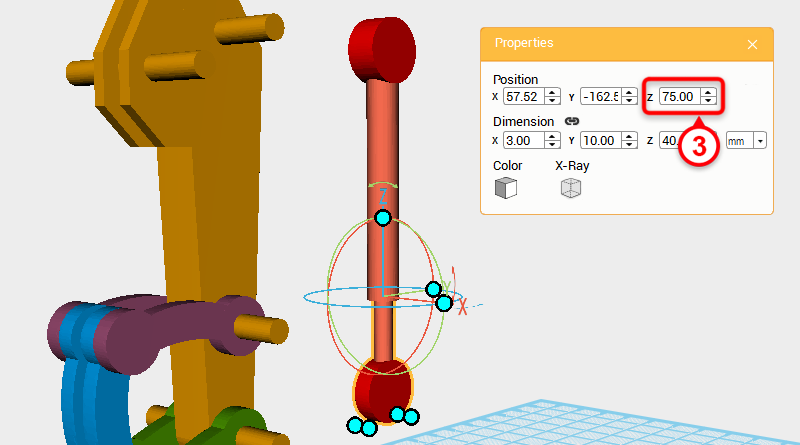 Drag select the two cylinders below and change their Z axis position to 75 so that they intersect with the upper cylinders.
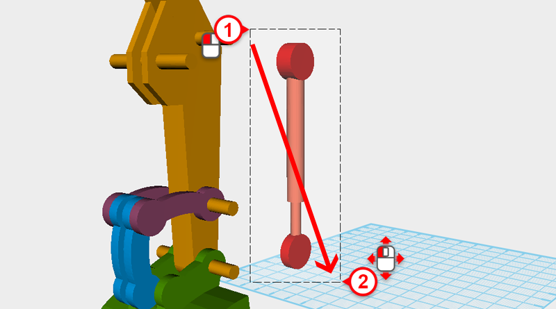
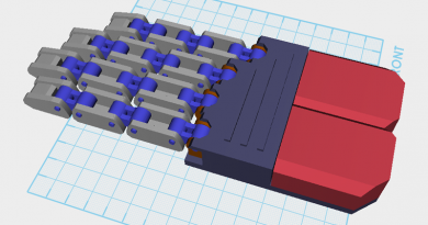
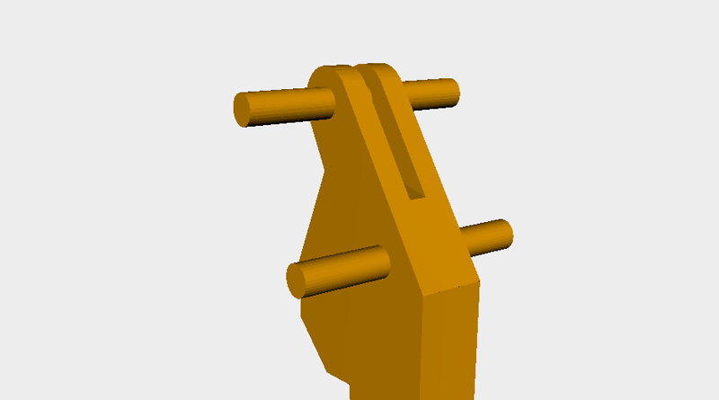
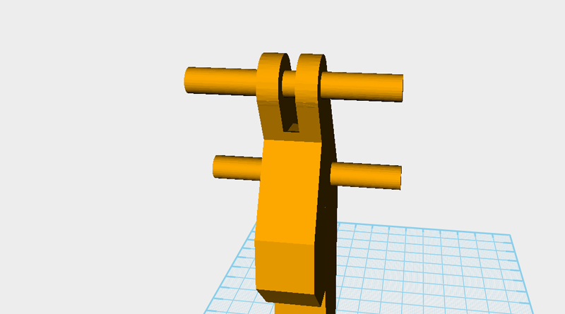
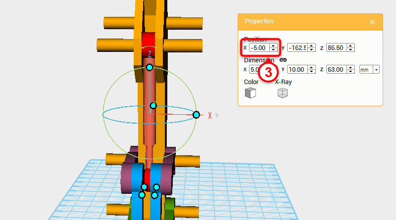 As shown in the image, drag select the four cylinders and change their X axis positions to -5.
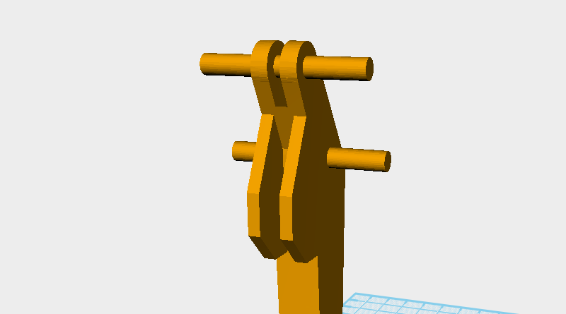
 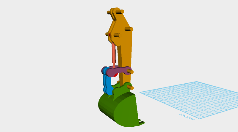 So far the digging arm should look as above, check the image with your model for any errors, then save the file.