XYZmaker tutorial – the Excavator part 9
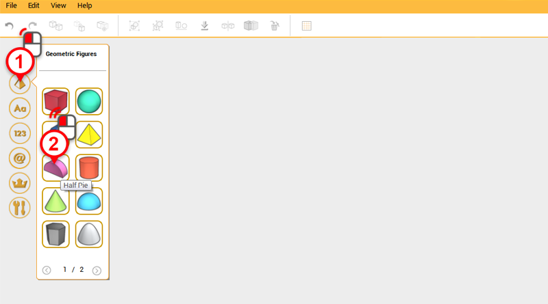
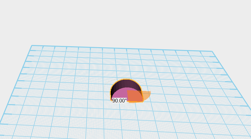
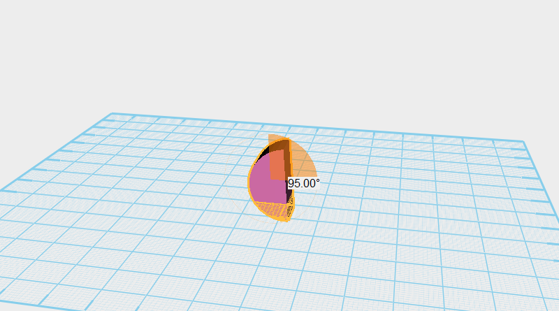 Next continue making the excavator bucket. Create a Half pie part and rotate it 90 ° along the Z axis, then again 95 ° along the X axis. Call this part the bucket.
 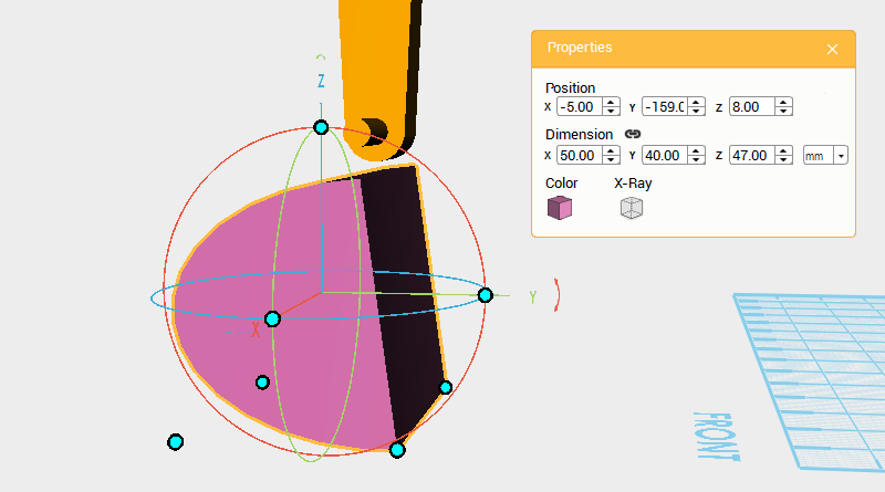 Change the bucket’s dimensions to X: 50,Y: 40,Z: 47 mm and position to X: -5,Y: -159,Z: 8.
 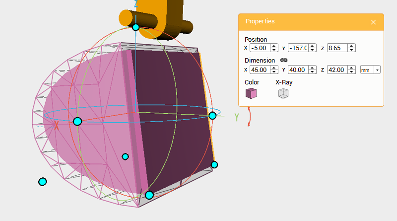 Clone the bucket and call this part the cutting part. Change the cutting part’s dimensions to X: 45,Y: 40,Z: 42 mm and position to X: -5,Y: -157,Z: 8.65.
 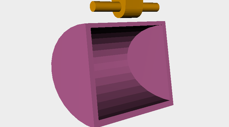 Use the cutting part and the Hole function to cut a cavity in the bucket.
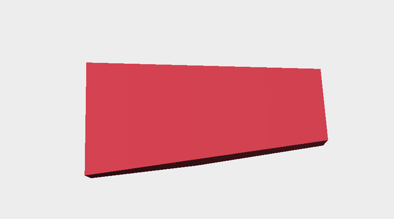
 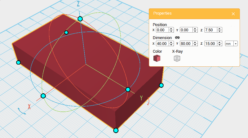 Next make the teeth for the bucket, first you will make a larger part and after cutting the outside of the part, shrink it so that it fits with the bucket. Create a cube and change its dimensions to X: 40,Y: 80,Z: 15 mm and position to X: 0,Y: 0,Z: 7.5. This will be the teeth.
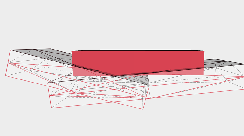
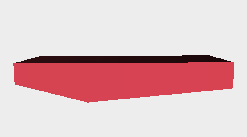 Create two cubes and adjust their dimensions, angle, and position as shown in the image. Next use the Hole function to cut away the teeth’s underside chamfer.
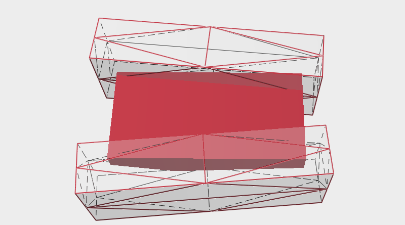
 Continue and create another two cubes and adjust their dimensions, angle, and position like the image above. Use the Hole function to cut away the teeth’s left and right side chamfer.
 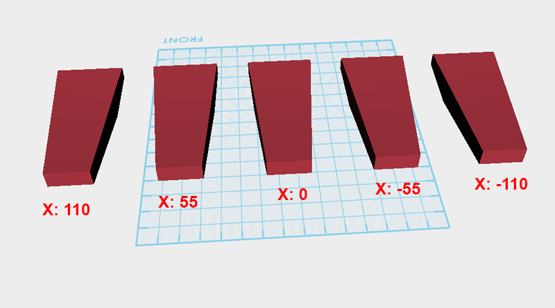 Clone the teeth 4 times, and change the X axis positions of each part as shown above so that each tooth is evenly spaced 55mm apart along the X axis.
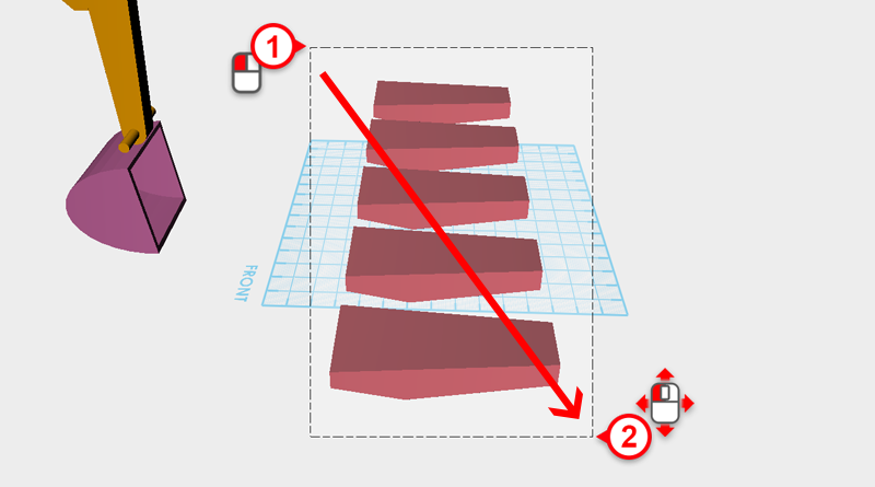
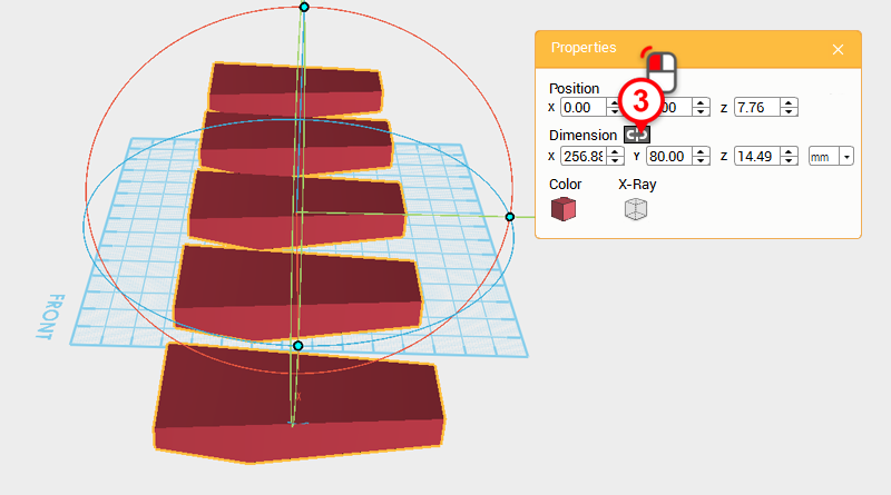
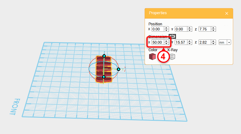 Drag select all the teeth and in the Properties window click on the Lock button. Next change the X axis dimension to 50mm to scale all the teeth proportionately to fit within a width of 50mm.
 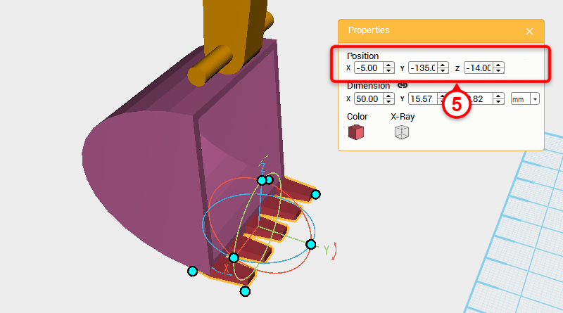 Lastly in the Properties window change the part’s position to X: -5,Y: -135,Z: -14 so that they assemble to make the bucket part.
 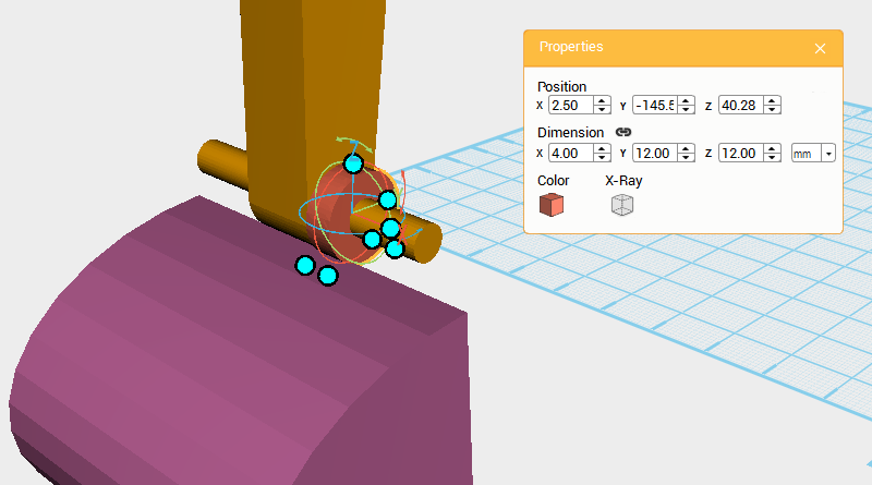 Create a Cylinder and change its dimensions to X: 4,Y: 12,Z: 12 mm and position to X: 2.5,Y: 145.59,Z: 40.28.
 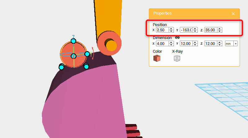 Clone the cylinder and change its position to X: 2.5,Y: -163,Z: 35.
 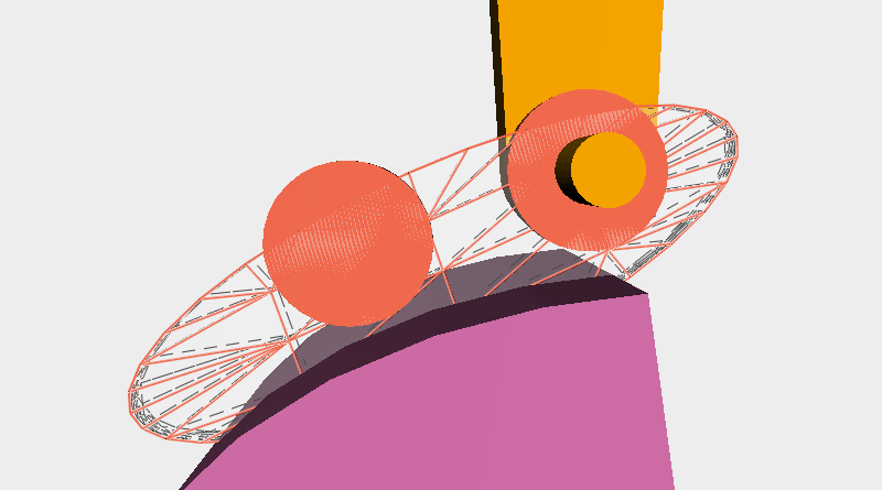 Clone the cylinder and adjust its position, dimensions, and angle to look as shown.
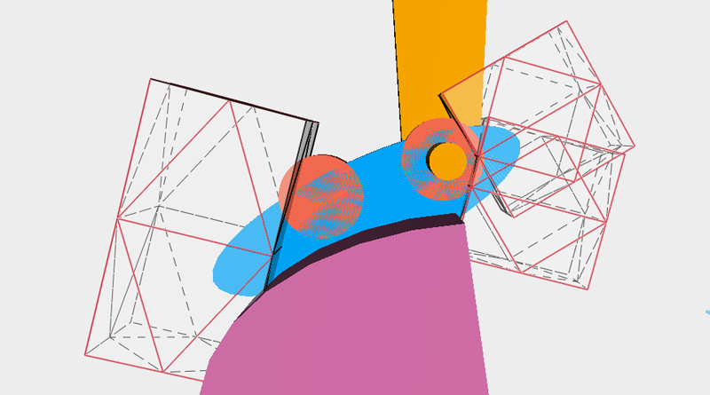
 Create a cube and adjust its position so that it’s in the right spot. As shown above use this part as a cutting part to remove the excess areas of the blue part.
 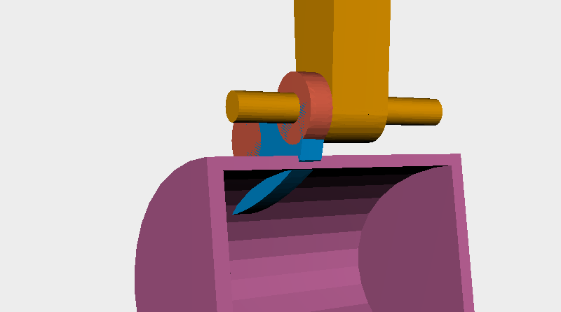 Inspect the model and you will find a part is sticking through the inside of the bucket.
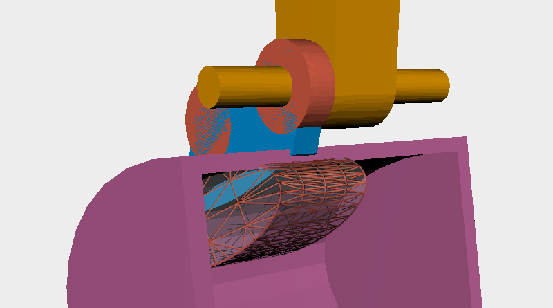
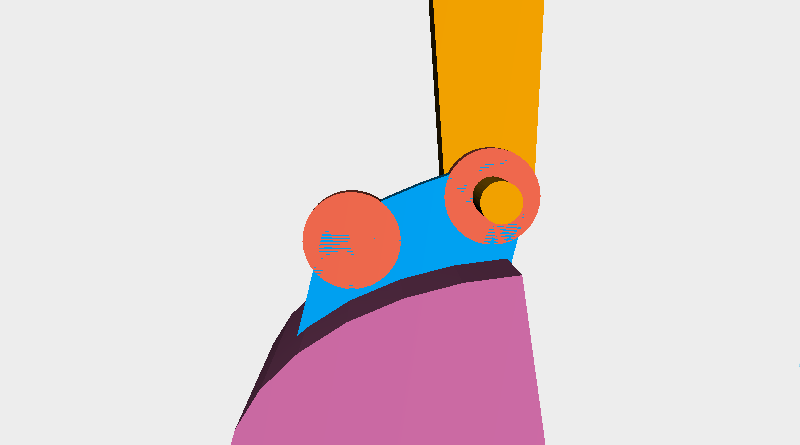
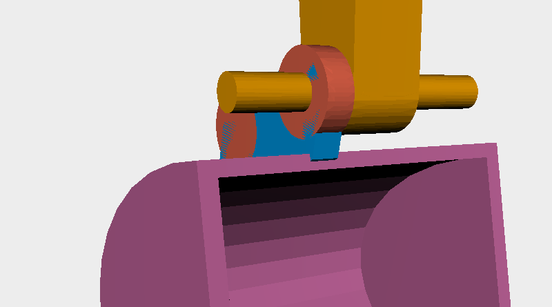 The same as before, create a part called the cutting part to cut away the area that is sticking through.
 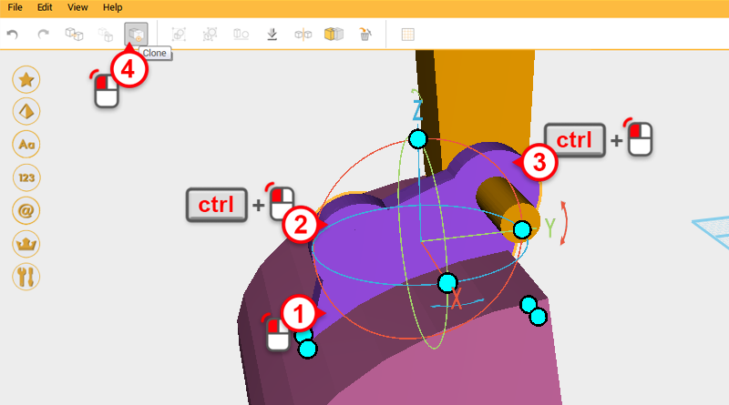 Select the three parts shown in the image and click on the Clone button.
 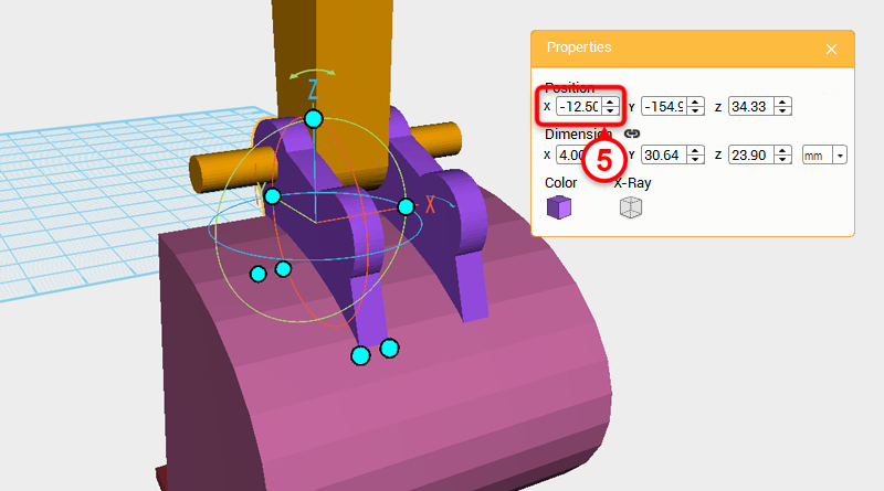 Change the copied part’s X axis dimension to -12.5
 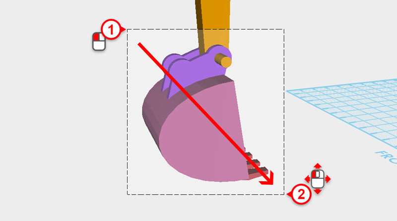 As shown above, drag select all the parts around the bucket.
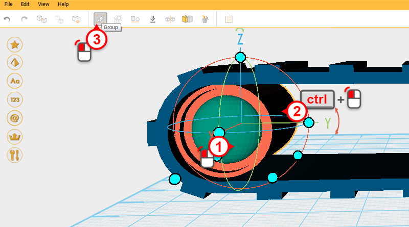
 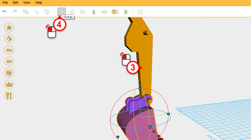 Press and hold the ctrl button and click the boom part to remove it from the selection. Click on the Group button to finish the bucket.
 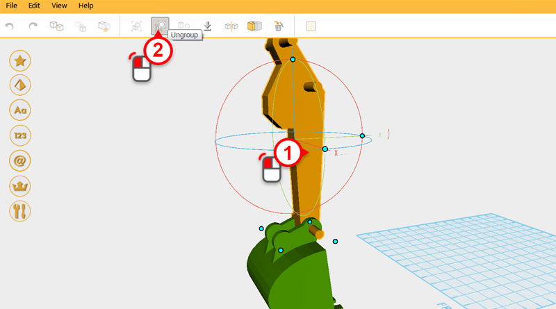 Most of the excavator’s main structure is already finished, all that is left are some connectors and hydraulics. Select the boom and click on the Ungroup button.
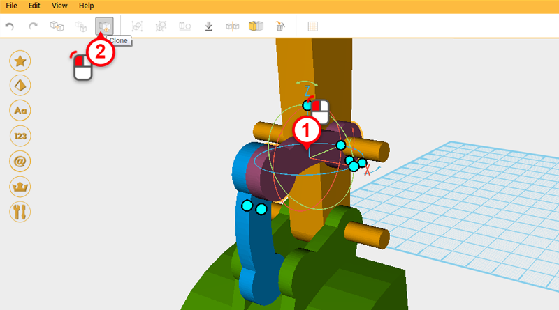
 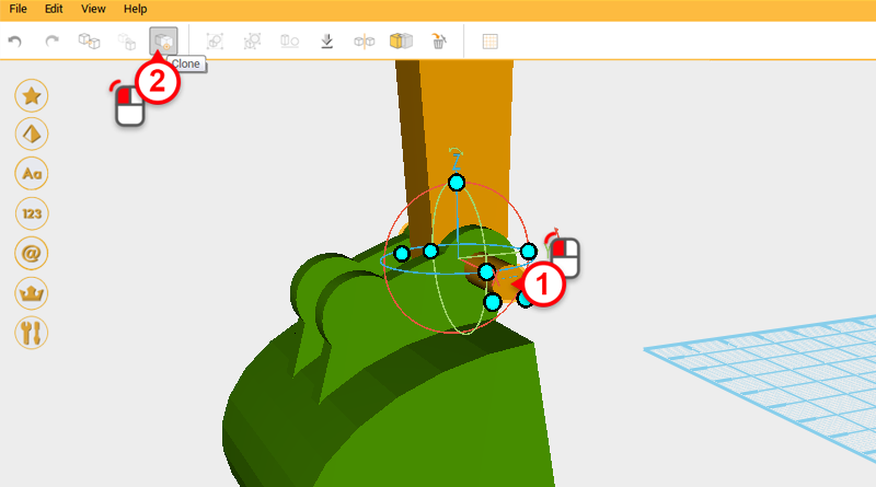 Select the cylinder in the image above and click on the Clone button.
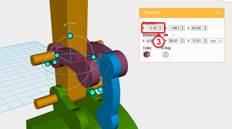
 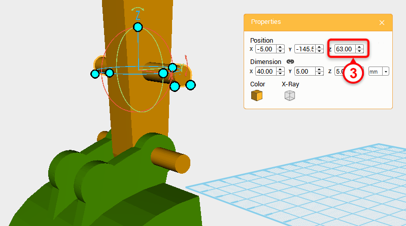 Change the copied cylinder’s Z axis position to 63.
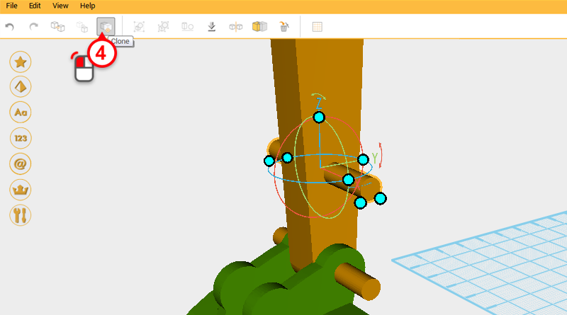
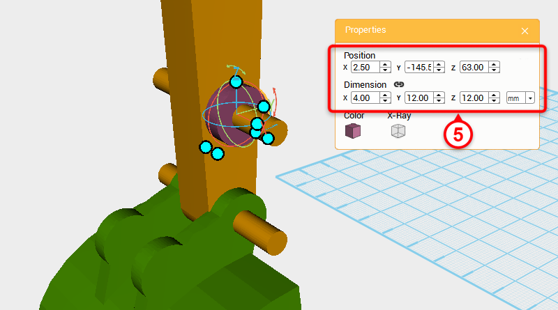 Click on the Clone button again and change the copied part’s dimensions to X: 4,Y: 12,Z: 12 mm and X axis position to 2.5.
 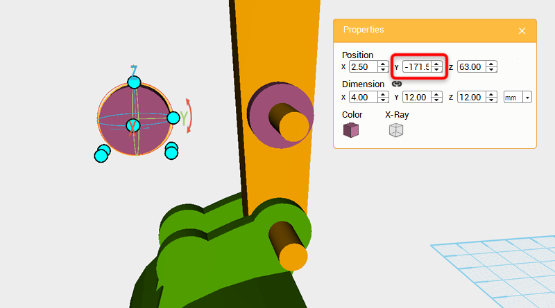 Clone the purple cylinder in the image and change its Y axis position to -171.59.
 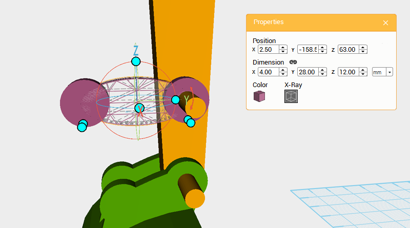 Clone the purple cylinder again and change its Y axis dimension to 28mm and Y axis position to -158.59.
 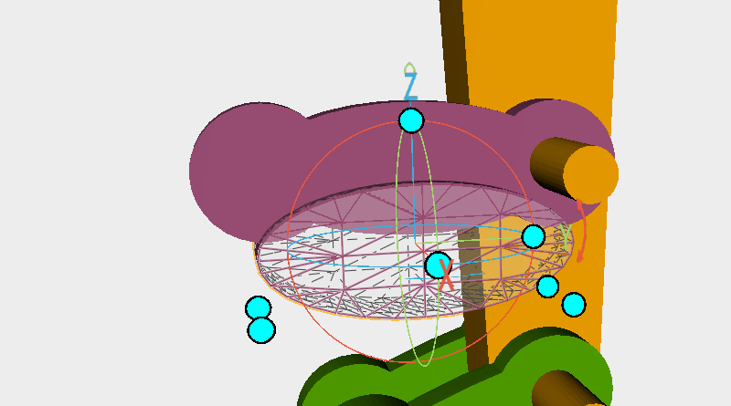 Clone the cylinder and enlarge the part along X axis, as above move the part down and call it a cutting part.
 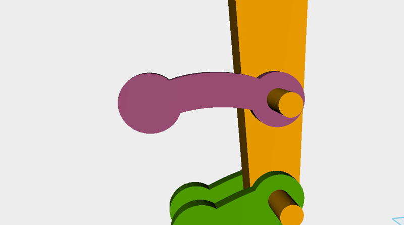 Use the cutting part and the Hole function to trim the top cylinder.
 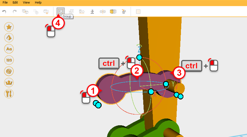 Select all three purple parts and click on the Group button to finish the connector.
 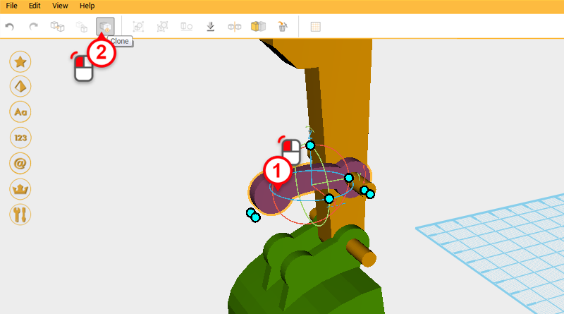 Select the connector and click Clone.
 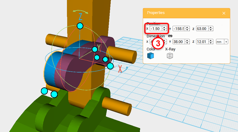 Change the cloned connector’s X axis to -1.5.
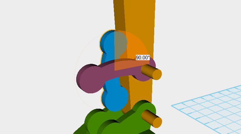
 Rotate the blue part in the image above 90° along the X axis, then adjust the Y axis and Z axis positions so that the part looks as above.
Tip:The X axis position needs to be set to 1.5
 Clone the purple connector and change the copied part’s X axis position to -12.5.
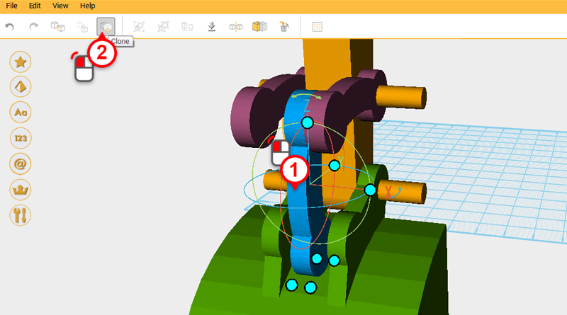
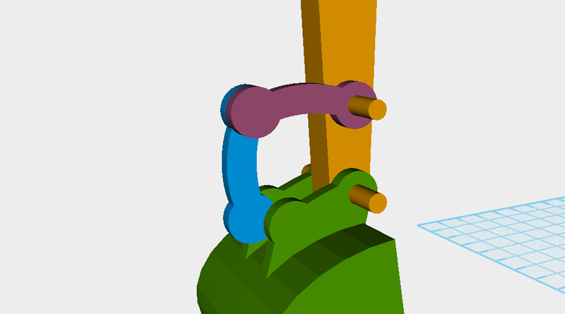
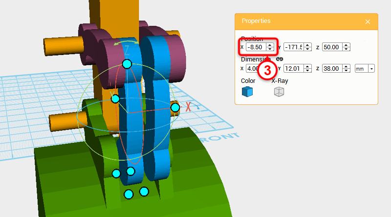 Clone the blue connector and change its X axis position to -8.5
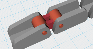
 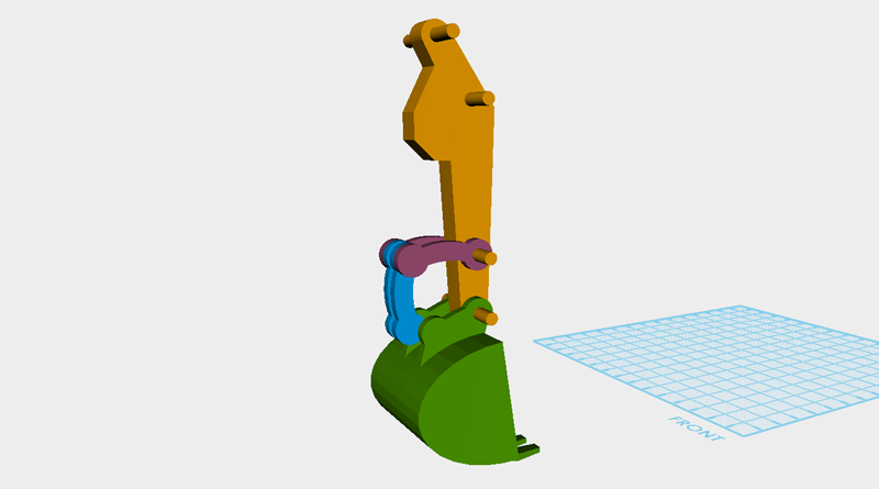 So far the model should look like the image above.