XYZmaker tutorial – the Excavator part 3
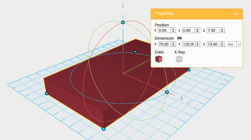 Next you want to make the chassis using the dimensions from the two tracks we just created. The left and right track’s dimensions are 70mm apart, 138mm long, and 28mm high. Use these measurements as a reference when creating the chassis. Create a cube and change its dimensions to X: 70,Y: 120,Z: 15 mm and position to X: 0,Y: 0,Z: 7.5. Call this part the chassis.
 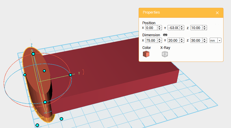 The front of the chassis has a concave recess. Create two cylinders, select one and change its dimensions to X: 75,Y: 20,Z: 30 mm and move it to the following position, X: 0,Y: -63,Z: 10.
 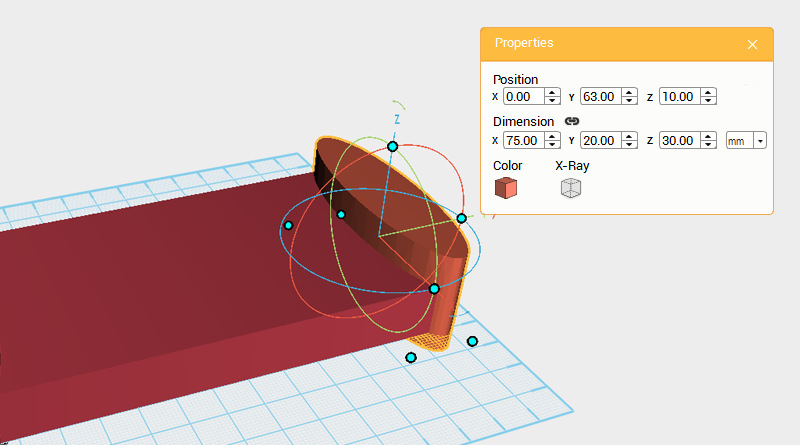 Change the other cylinder’s dimensions to X: 75,Y: 20,Z: 30 mm and move it to the back by changing its position to X: 0,Y: 63,Z: 10.
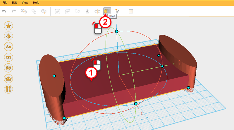
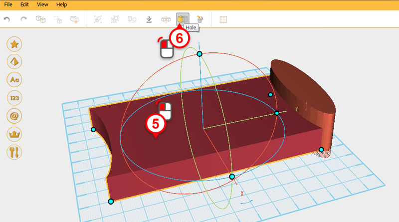
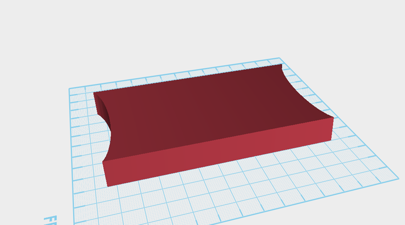 Use the two cylinders and the hole function to cut away two recesses from the base as shown in the image above.
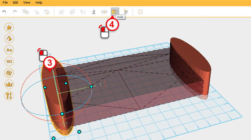
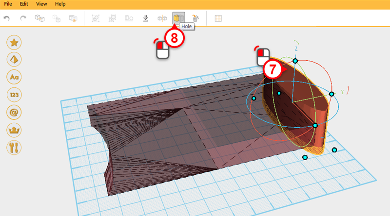
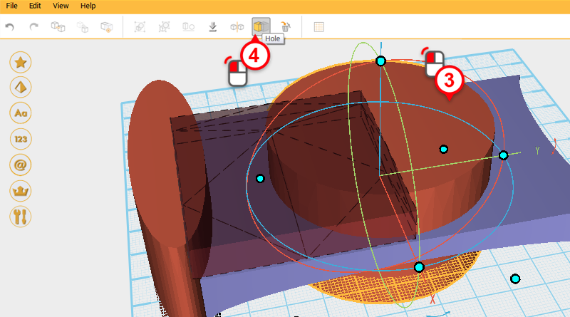
 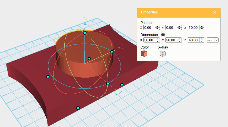 Next you need to cut away a hole from the chassis for the body part to sit in. Create a cylinder and change its dimensions to X: 50,Y: 50,Z: 40 mm and position to X: 0,Y: 0,Z: 10. Call this part cutting part.
 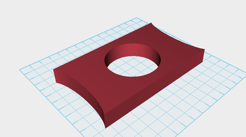 The same as before, use the cutting part and the hole function to cut a hole in the base.
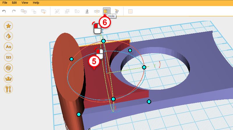
 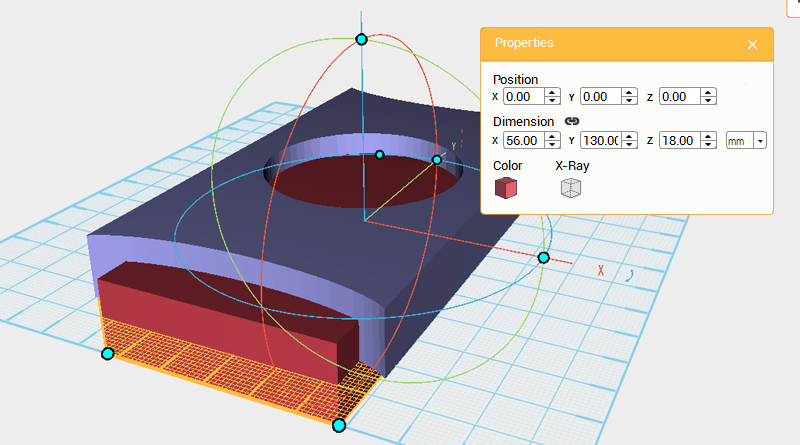 The chassis’ structure is pretty much finished, the next step is to shape the chassis’s exterior. One reason for this is to save on materials during 3D printing, the other reason is to make the model more refined. Create a cube and adjust its dimensions to X: 56,Y: 130,Z: 18 mm and position to X: 0,Y: 0,Z: 0. Call this part the cutting part.
 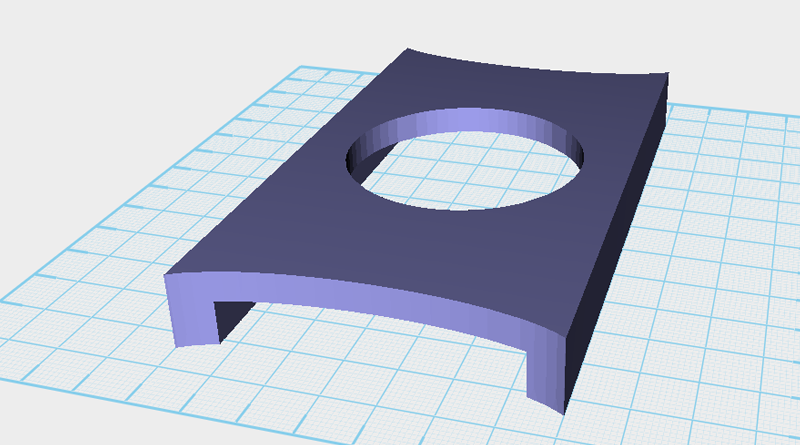 Use the cutting part and the Hole function to cut away the underside of the chassis.
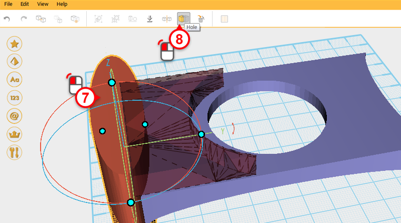
 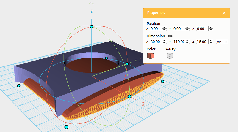 Create a cylinder and rotate it 90° along the Y axis, then change its dimensions to X: 80,Y: 110,Z: 15 mm and position to X: 0,Y: 0,Z: 0.
 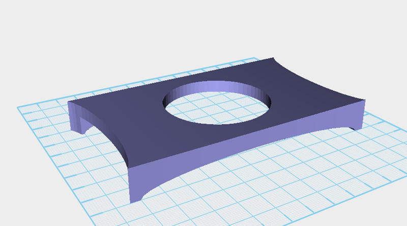 Continue to use the cutting part and Hole function to cut away from the chassis.
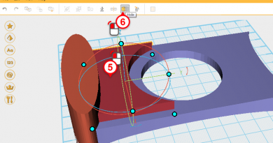
 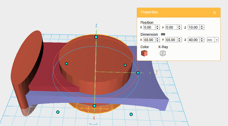 Continue to add to the structure of the chassis, increase the grouped chassis and body space, while also increasing the models layering. Create a cube and two cylinders, as shown above change the cylinder on the right’s dimensions to X: 65,Y: 65,Z: 40 mm and position to X: 0,Y: 0,Z: 10.
 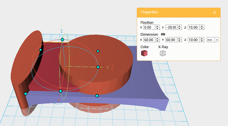 Change the cube’s dimensions to X: 60,Y: 60,Z: 10 mm and position to X: 0,Y: -28,Z: 16.
 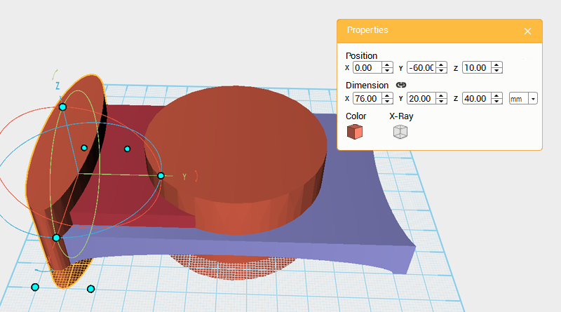 Take the cylinder on the left-hand side of the image and change its dimensions to X: 76,Y: 20,Z: 40 mm and position to X: 0,Y: -60,Z: 10.
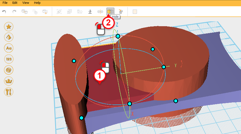
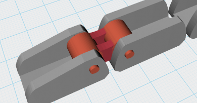
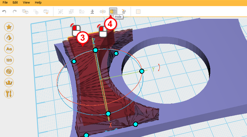
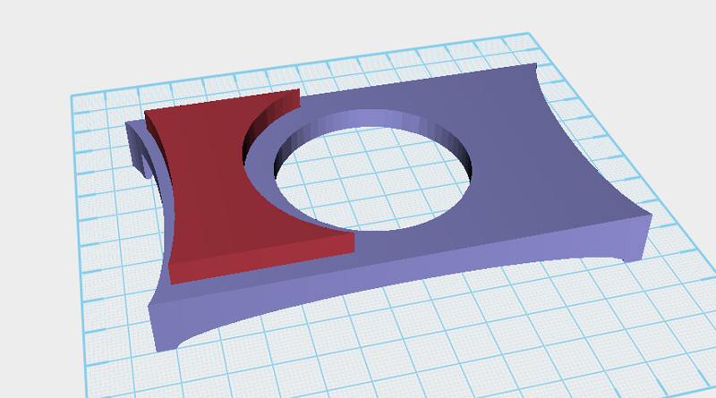 Use two cylinders and the Hole function and as shown in the image above cut to away from the cube. Call this the front frame.
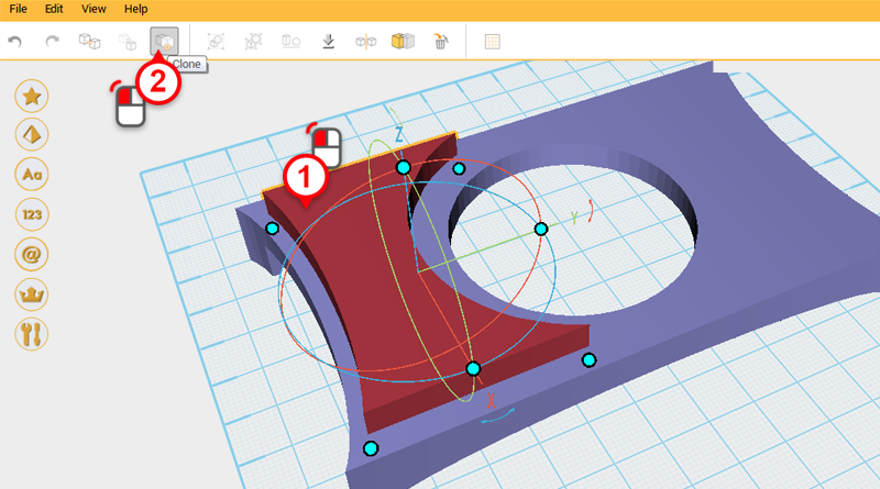
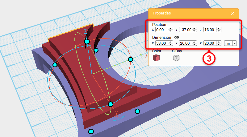 Select the front frame and click on the Clone button, take the new part and change its dimensions to X: 53,Y: 26,Z: 20mm. Call this part the cutting part.
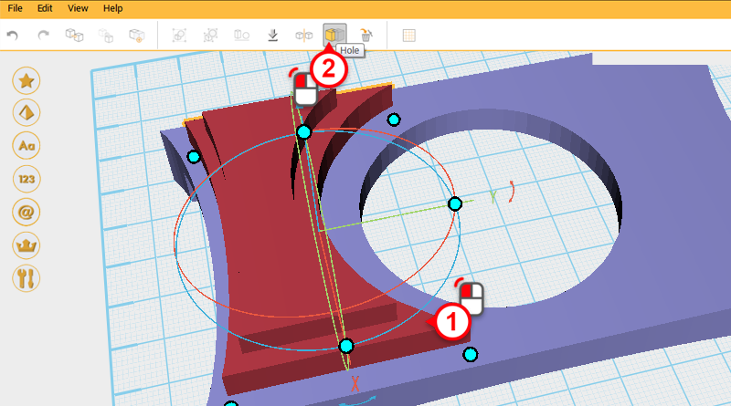
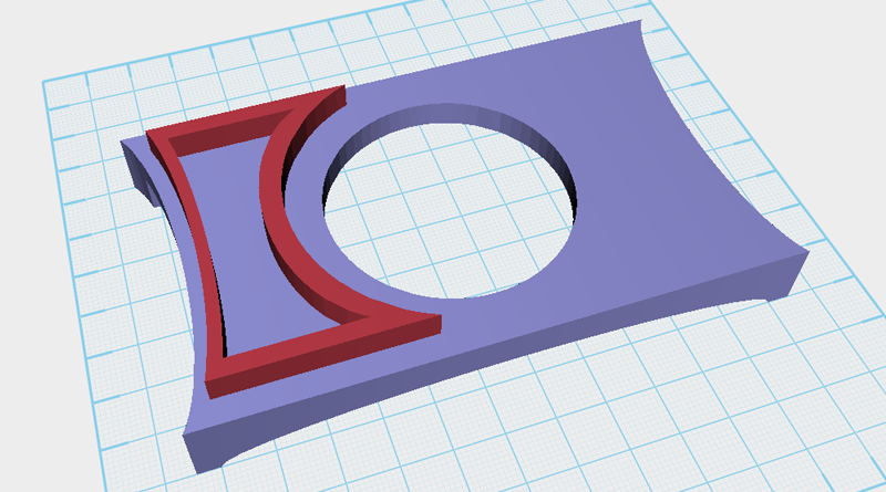 Use the cutting part and the Hole function to cut a hole in the front frame.
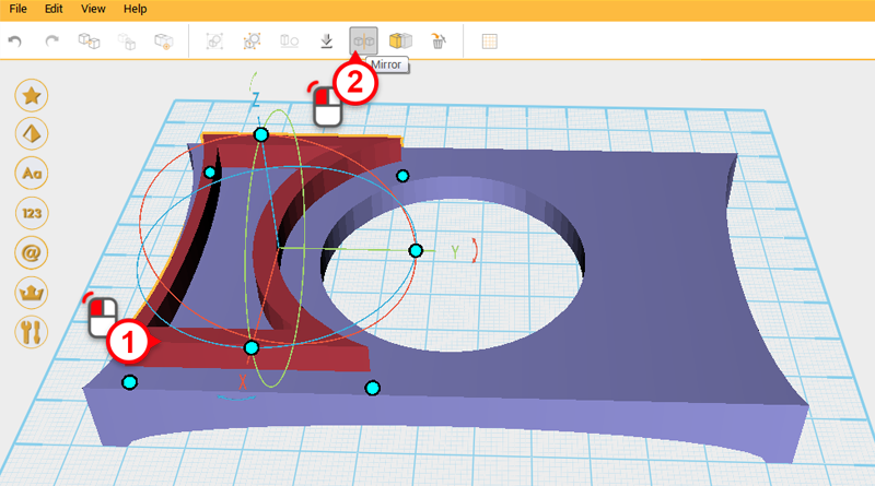
 Select the front frame and click on the Mirror button, then in the Mirror properties box click on the back button to mirror a back frame part.
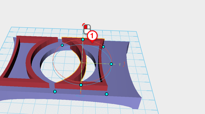
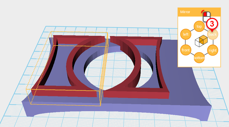
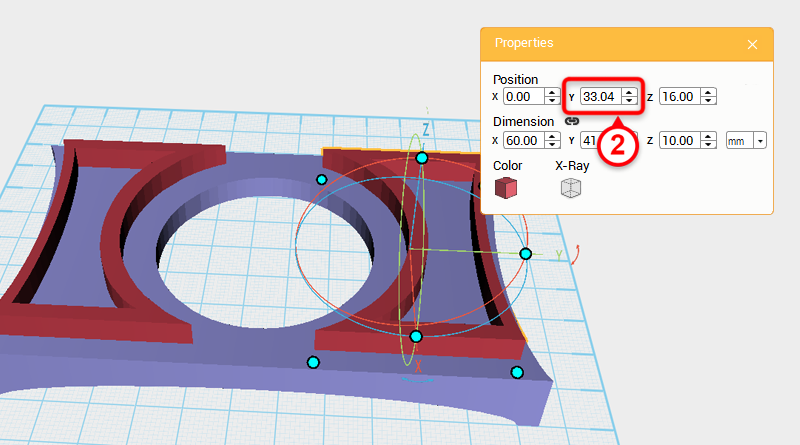 Select the back frame and change its Y axis position to 33.04.
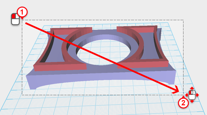
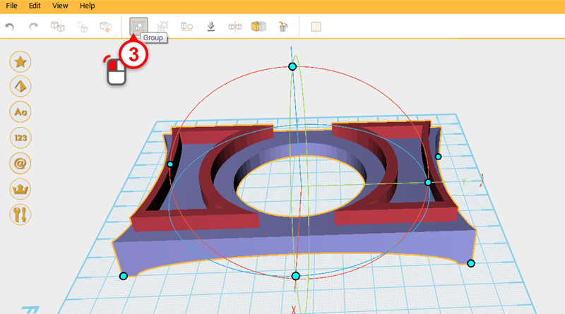 Drag select all the parts and click on the Group button to finish the chassis assembly.
 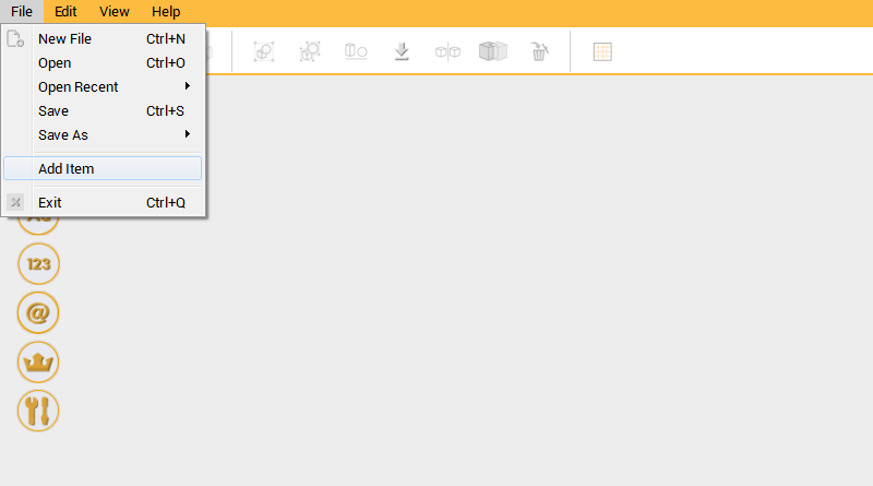 Next you need to check if the chassis assembly and the track assembly match. Click on File in the Menu bar, then click on Add Item.
 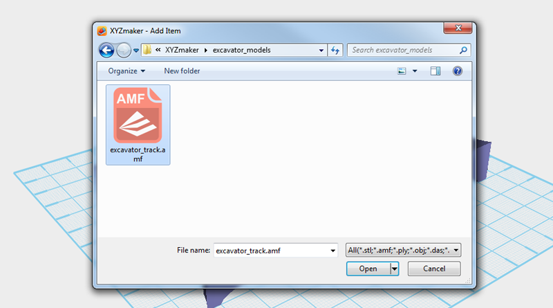 In the file browser window select excavator_track.amf to add the track support to the file you are currently working on.
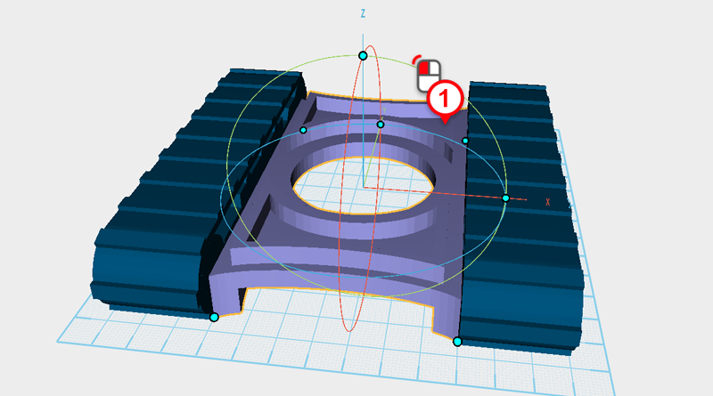
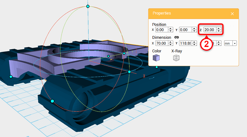 The chassis assembly and left and right track support match, but the height needs to be increased. Select the chassis assembly and change its Z axis position to 20, you will be able to see that the chassis assembly height is over the track assembly. This way when the track is combined with the chassis the two won’t rub.
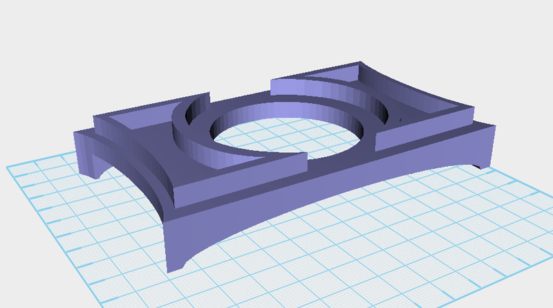
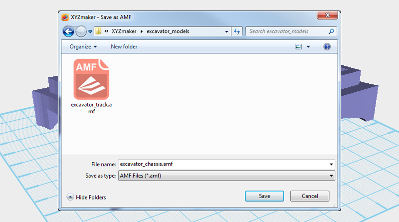 Delete the track assembly so that only the chassis assembly remains, then save the file as excavator_chassis.amf.