XYZmaker tutorial – the Excavator part 8
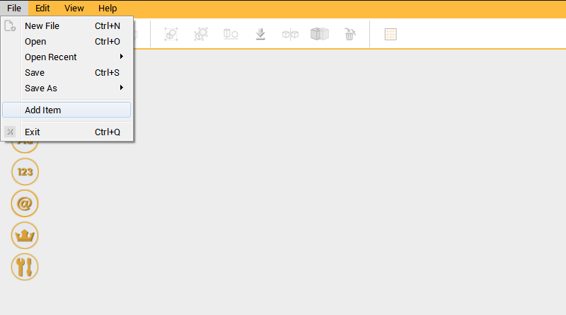 Before making the digging arm, you first need to set the boom’s position. To add the file excavator_boom.amf, go the Menu bar and under File, click on Add Item.
 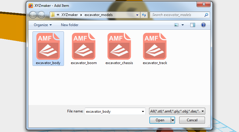 In Add item window select excavator_body.amf to add the body assembly to the excavator body assembly.
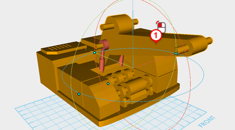
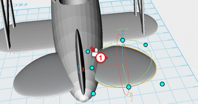
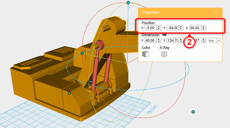 Select the boom assembly and change the position to X: -5,Y: -84,Z: 86.66.
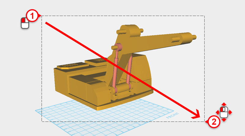
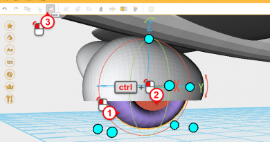
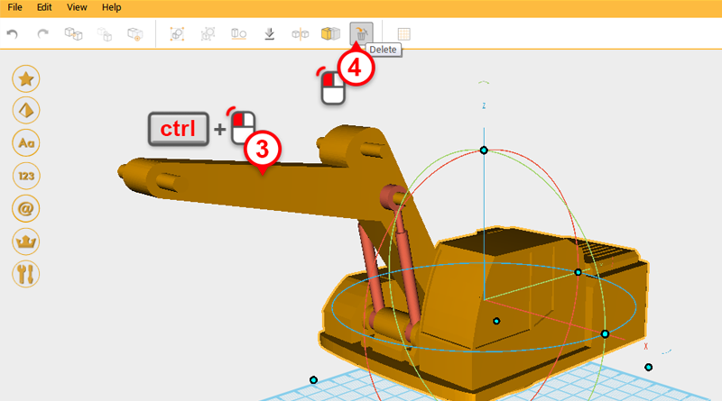 Drag select all the parts and with ctrl button pressed, click on the boom assembly to remove it from the selection. Click on the Delete button or press the delete key to delete the body.
 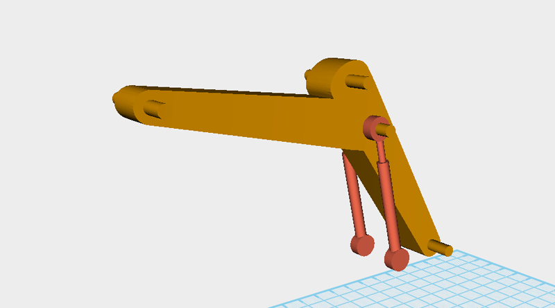 Save the remaining Boom assembly.
 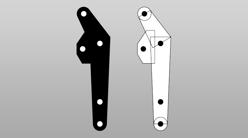 When modeling the digging arm and the boom, first make a 2D drawing to plan out the shapes needed to model the part and at the same time plan the different hole positions.
 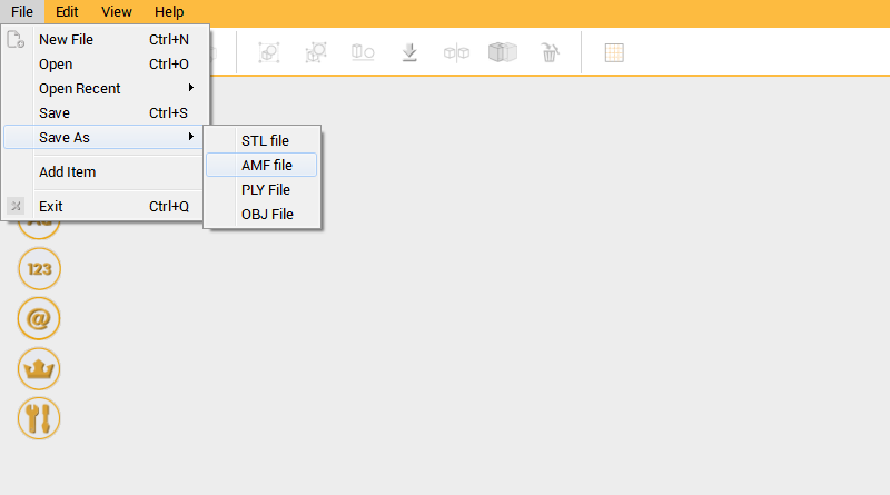 Because the digging arm and boom both have elements in common, you can use the boom model as a base when making the digging arm. Open excavator_boom.amf and go to Menu Bar > File > Save As > AMF file.
 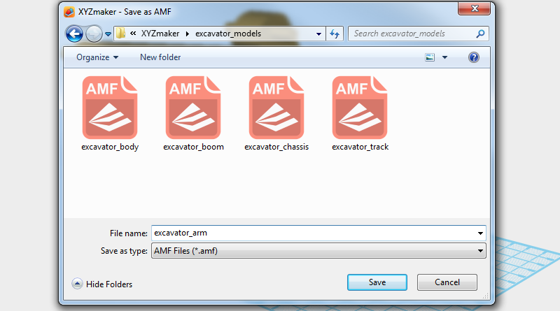 In the Save window change the file name to excavator_arm.amf.
 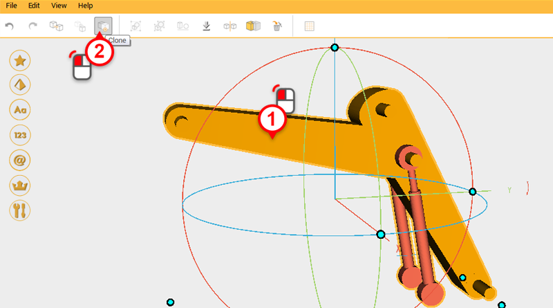 Select the boom assembly and click on the Clone button.
 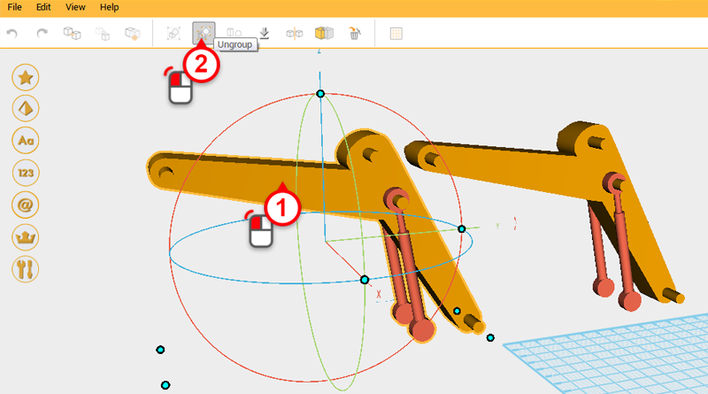 Move the cloned part to the front and click on the Ungroup button.
 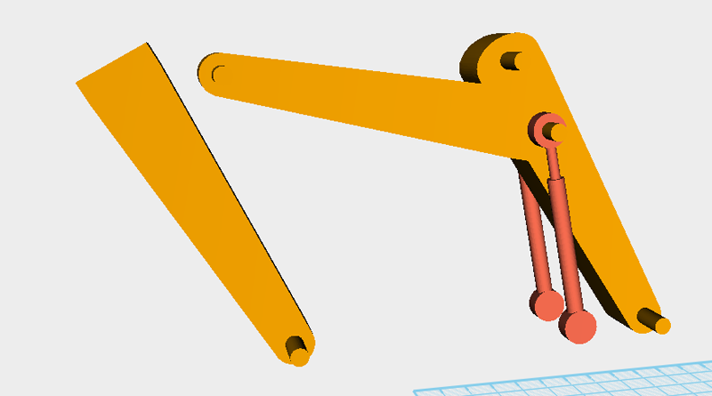 Select and delete the parts that you don’t need, leave the parts shown in the image above.
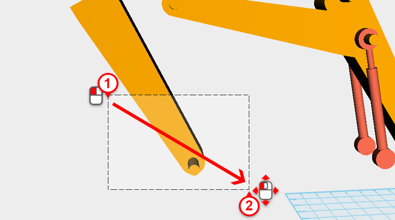
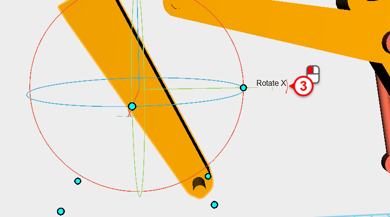
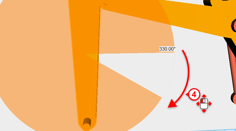 Drag select the remaining 3 parts that are in front and click on the arrow next to the Y axis, then drag and rotate it 330 degrees.
 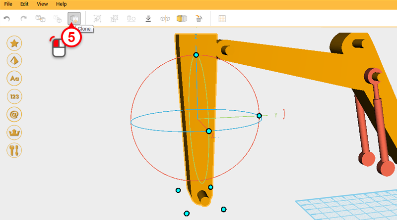 While the parts are still selected, click on the Clone button.
 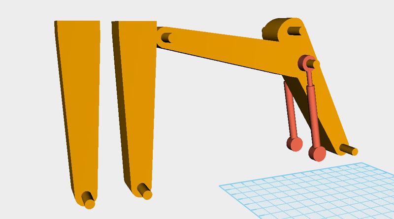 Move the duplicated part forward to the same area as the part in the image above.
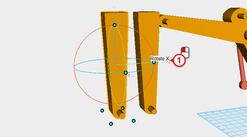
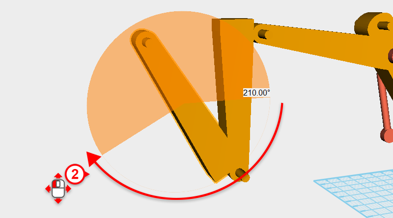 Click on the arrow next to the Y axis in the control orb and drag it down to rotate the part 210°
 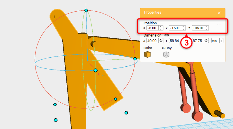 In the Properties window change the part’s position to X: -5,Y: -150,Z: 105.
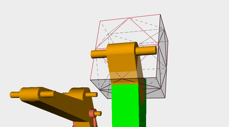
 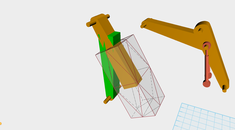 Next you want to cut away the overhanging areas. First take the boom assembly and move it to a place where it is out of the way. Create a cube, and after rotating and enlarging it, move it to the same position as the transparent cube in the image above.
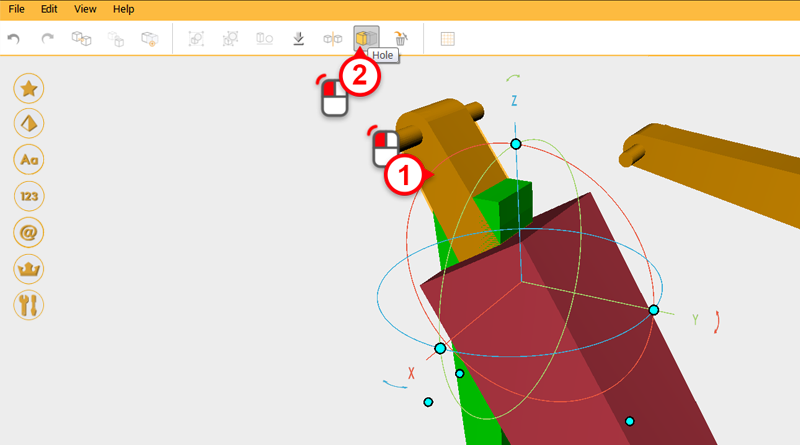
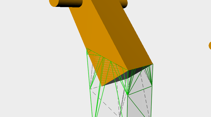
 Use the cube and the Hole function to cut away the excess areas. After cutting, the model should resemble the image above.
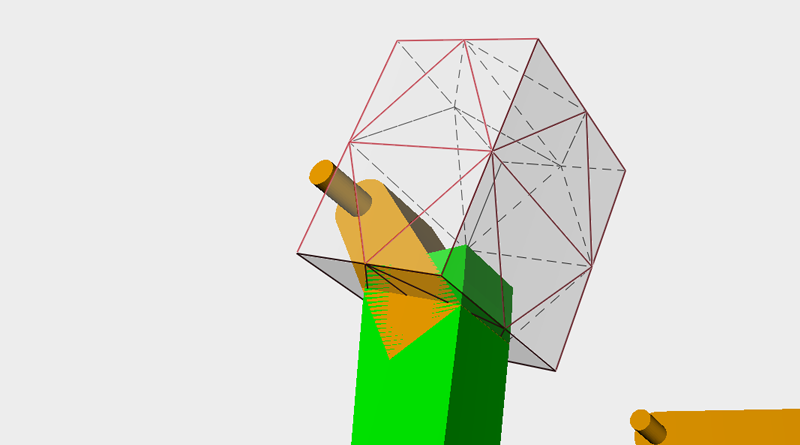
 Create another cube and rotate it, enlarge it, and move it to the same position as shown in the image above.
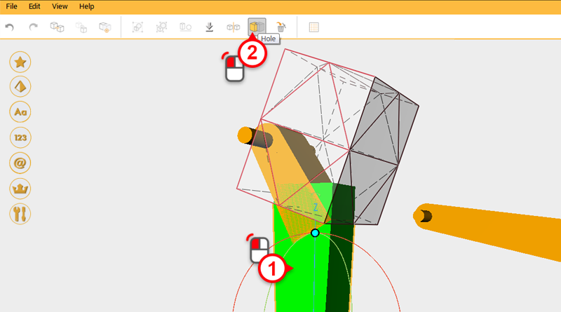
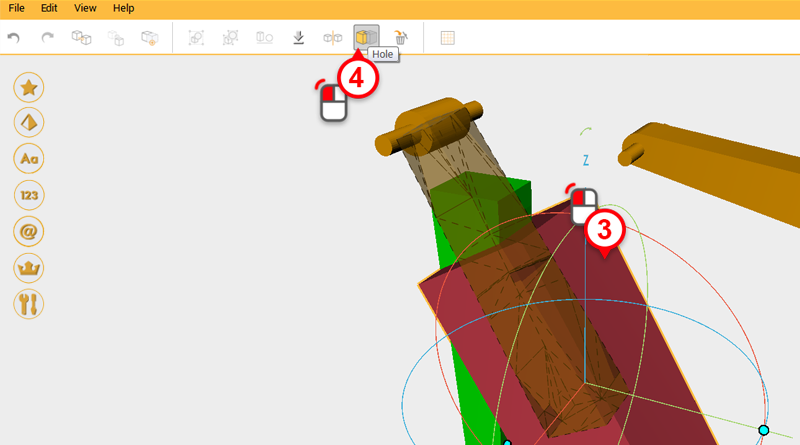
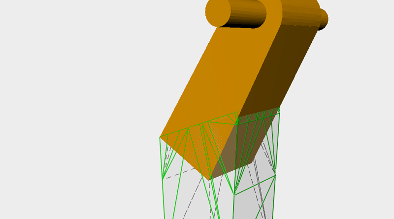
 Use the cube and the Hole function to cut away unwanted material from the green block in the image above.
Tip: This type of modeling can be complicated because you have to try a few times before you can get the desired effect, because of this, use the Undo tool often when trying to get the desired effect.
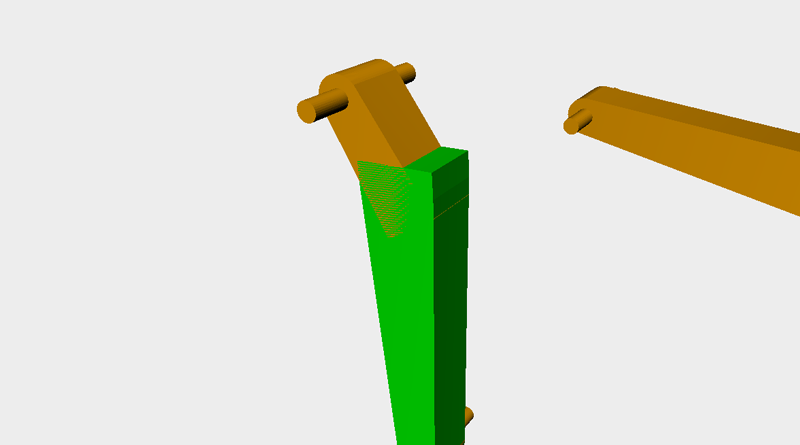
 When you have two matching parts their shape should look like this.
 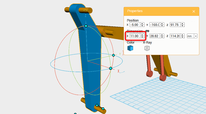 Take the boom assembly and move it back to its original position, select the blue part shown in the image above and change its X axis dimension to 11mm.
 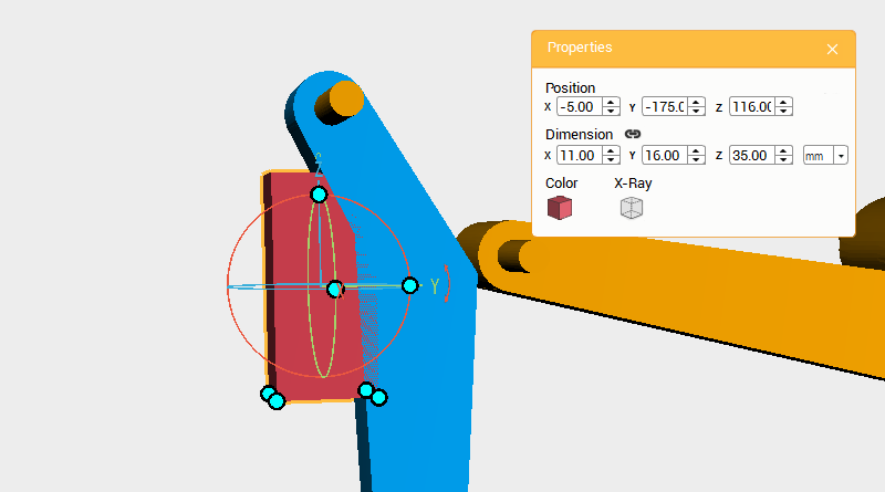 Create a cube and change its dimensions to X: 11,Y: 16,Z: 35 mm and position to X: -5,Y: -175,Z: 113.
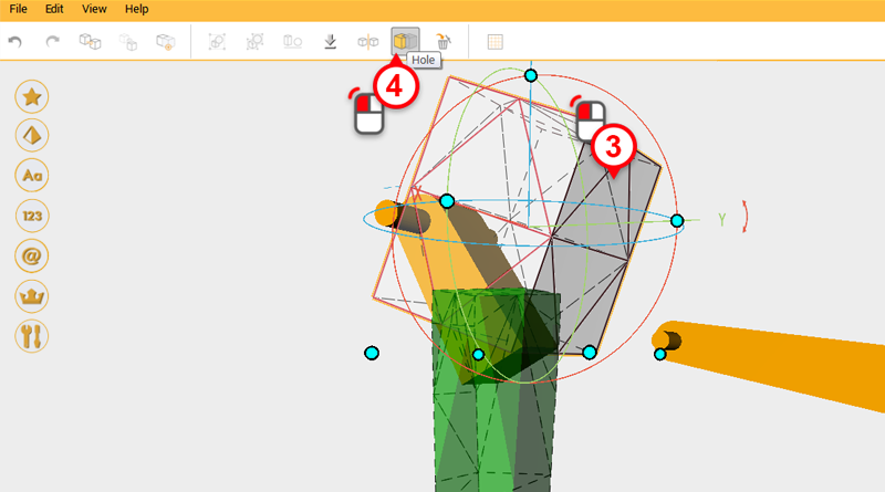
 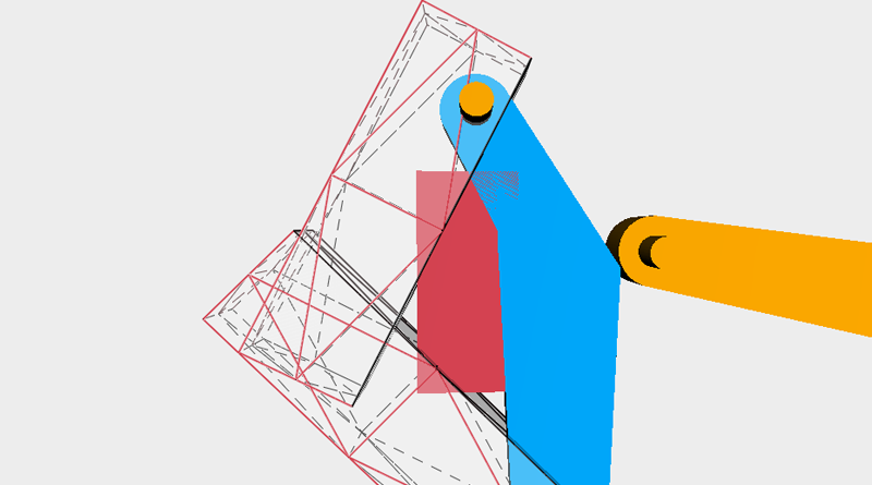 Create two cubes, rotate and enlarge them, then move them to the same position as the image above. Call these parts the cutting parts.
 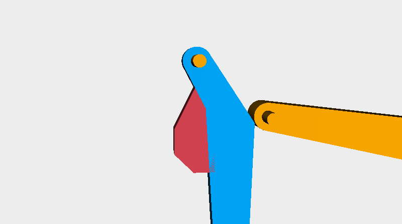 Use the cutting parts and the Hole function to cut the red shape above.
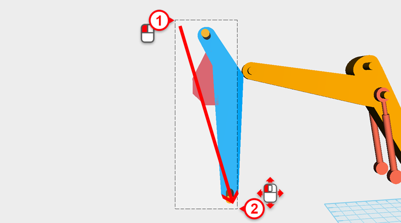
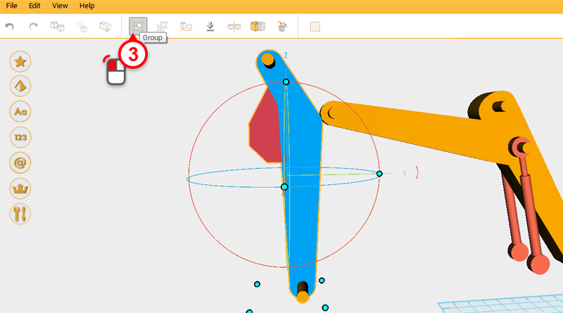 Drag select all the parts in front and click on the Group button. Call this part the digging arm.
 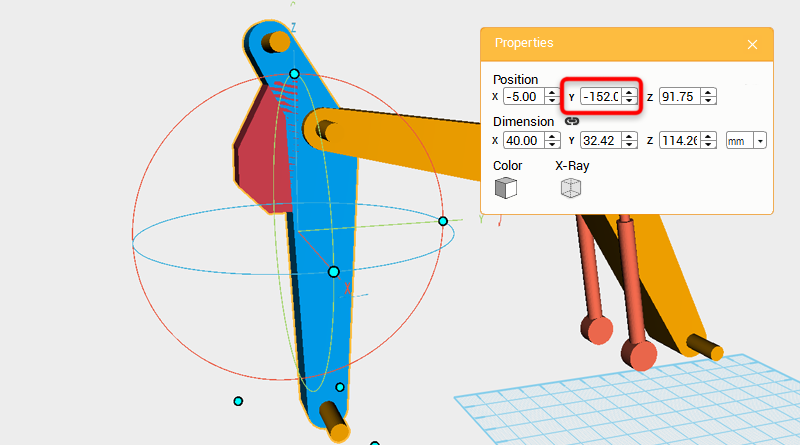 Change the digging arm’s Y axis position to -152.
 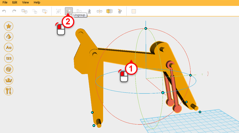 Select the boom assembly and click Ungroup.
 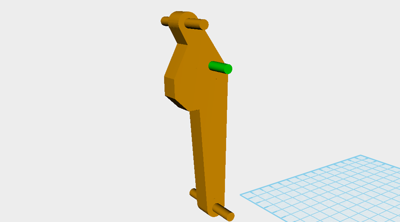 Apart from the green part above, delete all the parts in the boom assembly. The remaining parts should look as above.