XYZmaker tutorial – the Excavator part 7
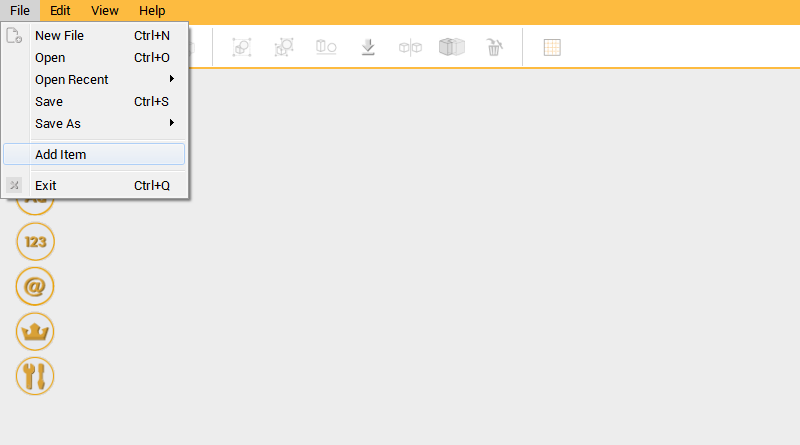 After completing the Boom part, add some more connecting features to the body part for connecting the boom to. Open the excavator_body.amf, click on the Menu bar then select File to use the Add item function.
 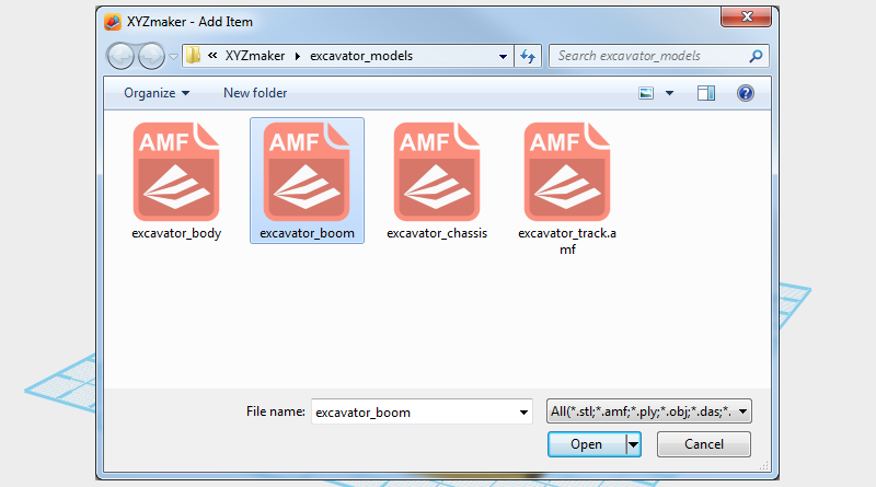 In Add item window select excavator_boom.amf to add the Boom assembly to the excavator body assembly.
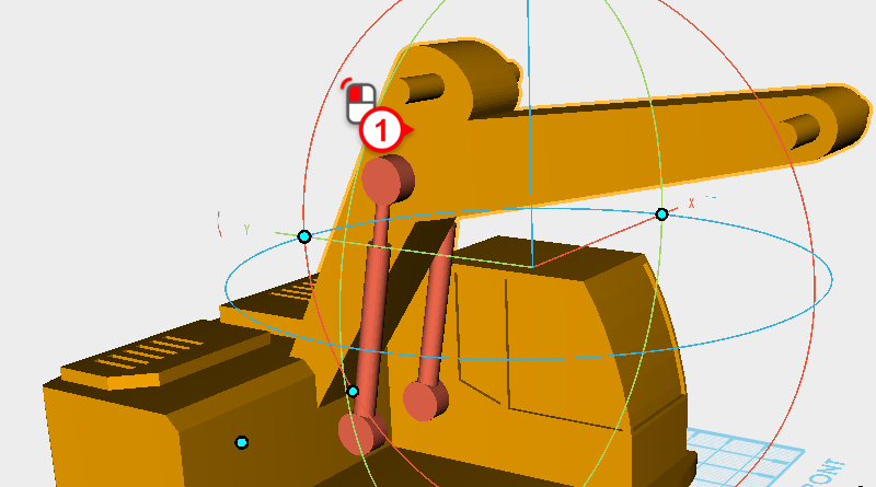
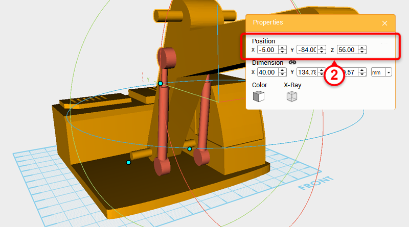 Select the boom assembly and change its position to X: -5,Y: -84,Z: 56.
 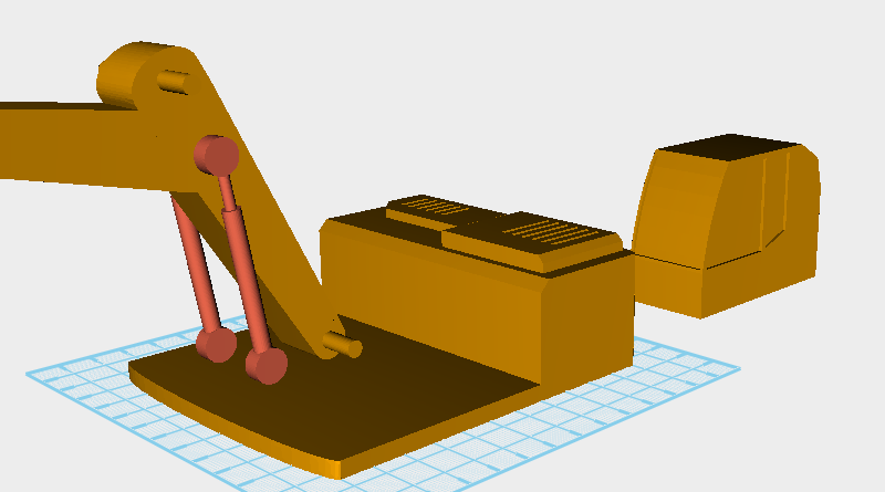 As shown in the image above, first select the driver cab and move it to the back to make it easier to model the other parts.
 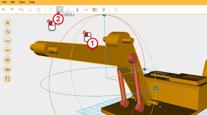 Next, create the body and hydraulic connecting link, select the hydraulic assembly and click on the Ungroup button.
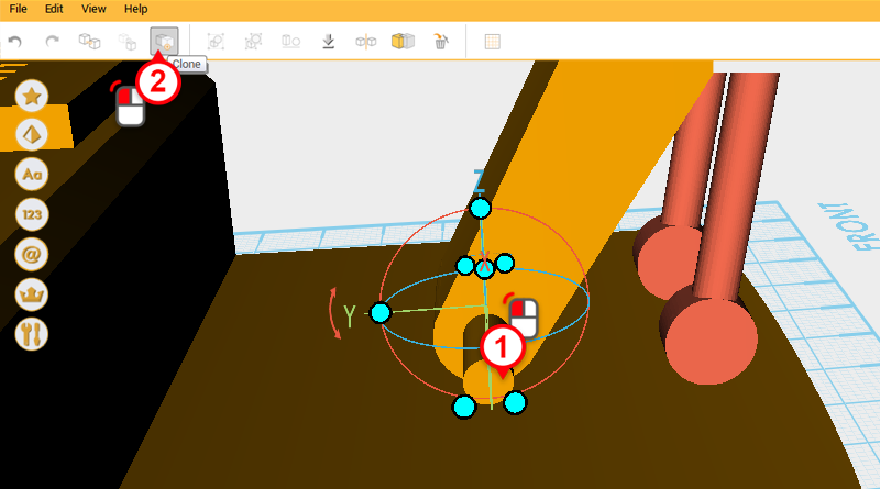
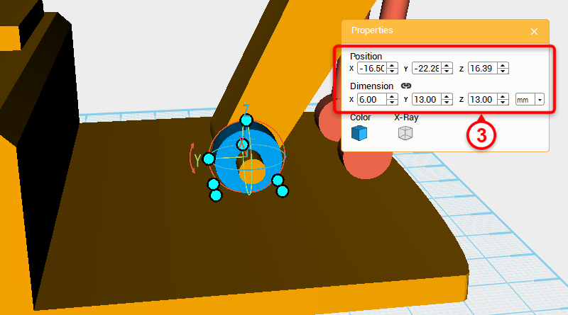 Select the cylinder shown in the image above and click on the Clone button. Next, change the cylinder’s dimensions to X: 6,Y: 13,Z: 13 mm and X axis position to -16.5.
Tip:You can change the color of the parts when modeling anytime to make it easier to see the different parts.
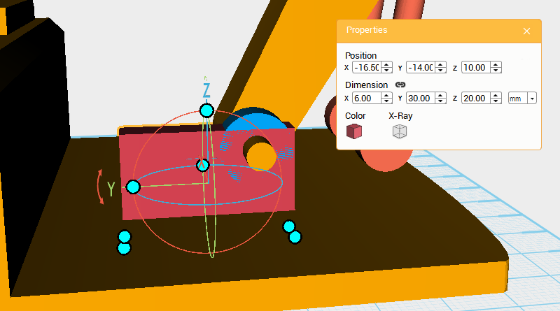 Create a cube and change its dimensions to X: 6,Y: 30,Z: 20 mm and position to X: -16.5,Y: -14,Z: 10.
 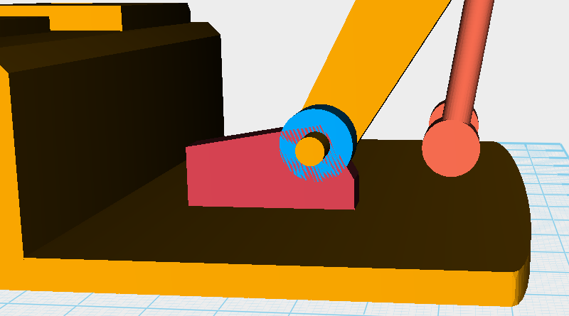 Clone the cube and use it as a cutting part, then as shown in the image above, use the Hole function to chamfer the edges of the original cube. Because this technique has already been used many times during this tutorial, there is no need to repeat it.
 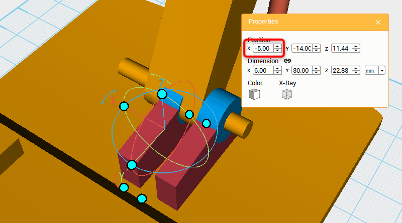 Select and Clone the cylinder and cube you created earlier, then change their X axis position to -5.
 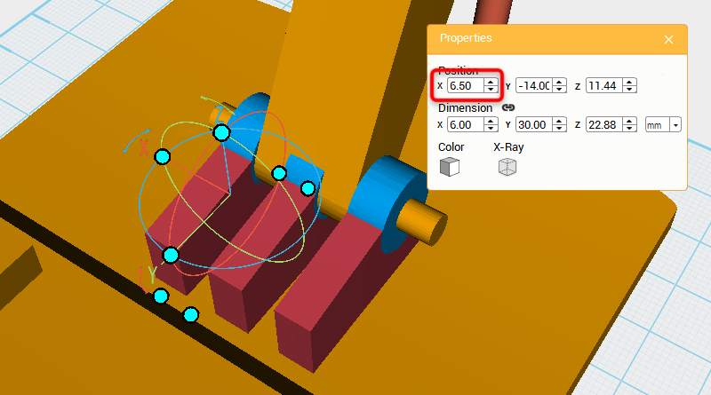 Select the cloned cylinder and cube again, then change their X axis position to 6.5.
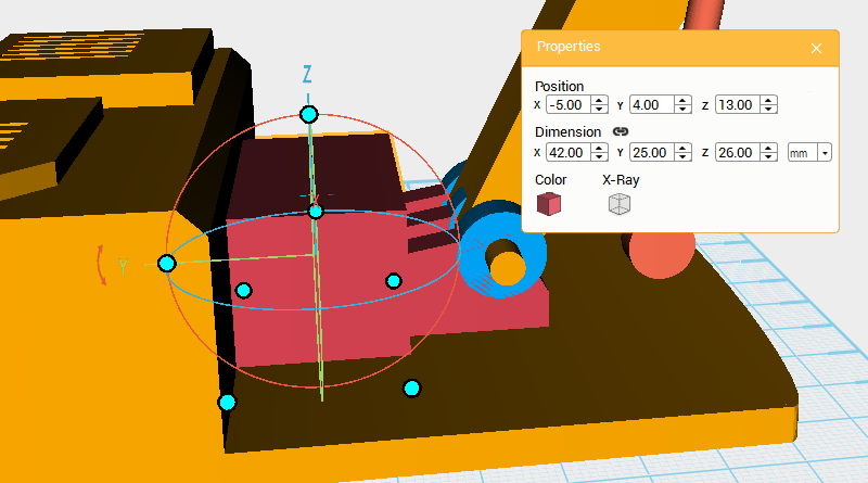
 As shown above create a cube and chamfer the edge.
 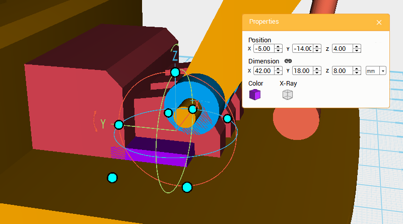 Make another cube and change the dimensions and position as shown above to add more detail to the model.
 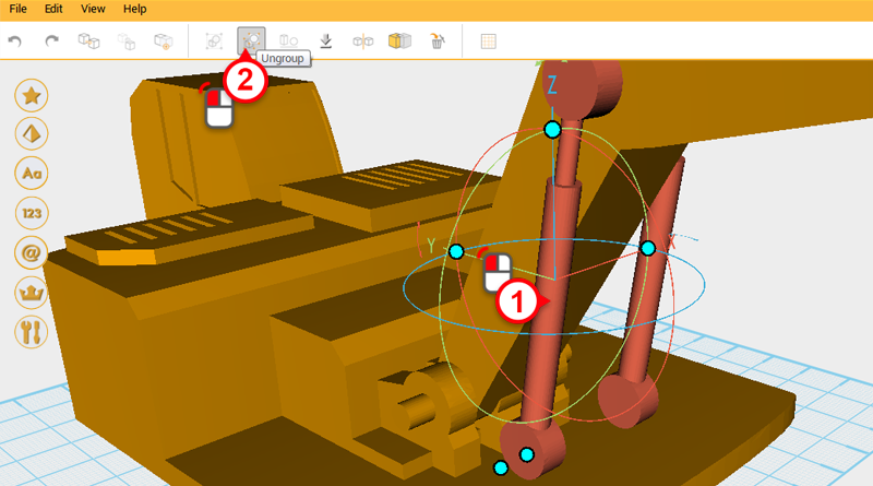 Next continue to make connecting links for the boom hydraulics. Select the left-hand side hydraulic and click on the Ungroup button to separate the components.
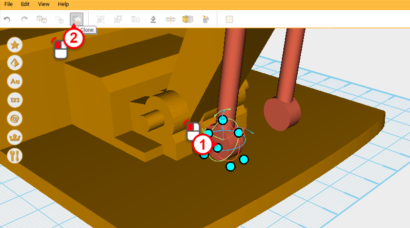
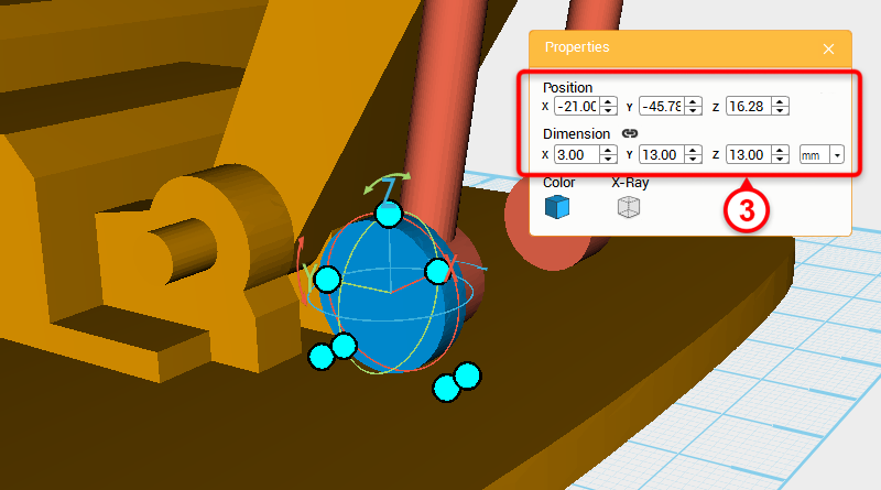 Select the cylinder in the center of the image and click on the Clone button. Next, change the dimensions to X: 3,Y: 13,Z: 13 mm and X axis position to -21.
 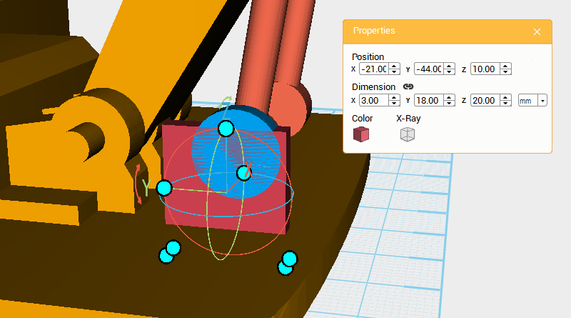 Create a cube, and change its dimensions to X: 3,Y: 18,Z: 20 mm and position to X: -21,Y: -44,Z: 10.
 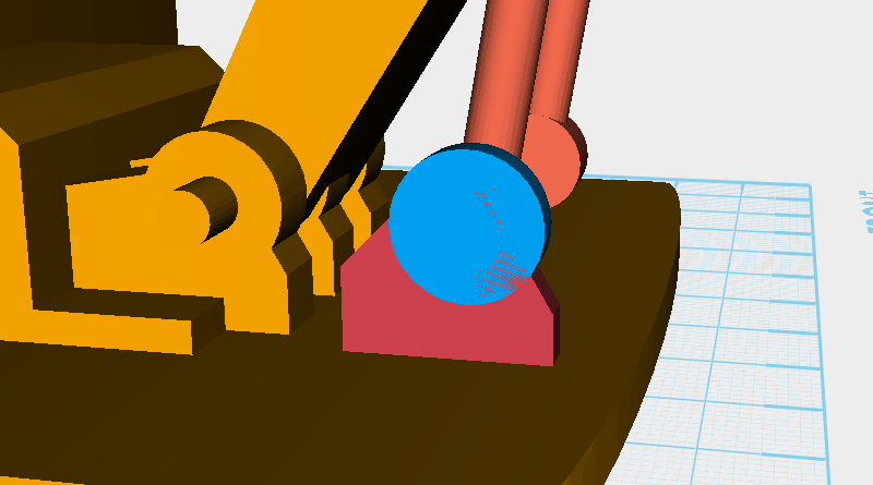 Clone the cube and use it as a cutting part to chamfer the edges of the original cube so that it looks like the image above.
 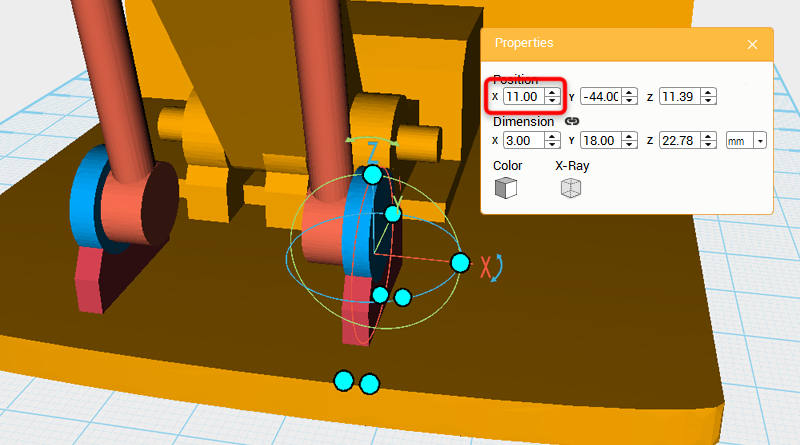 Select and clone the cylinder and cube you just created, then change the cloned part’s X axis position to 11.
 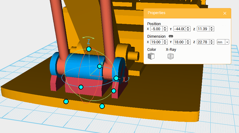 Select and clone the cylinder and cube again, then change these new parts X axis position to -5 and X axis dimension to 19mm.
 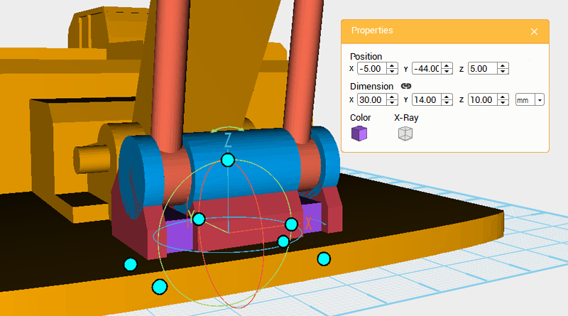 Lastly, create a cube and change its dimensions and position to the image above, this will make the structure look more covered up.
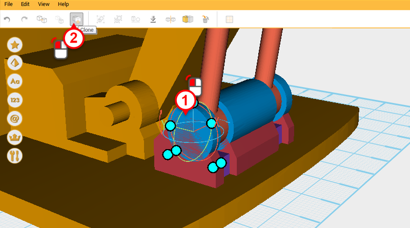
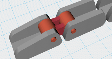
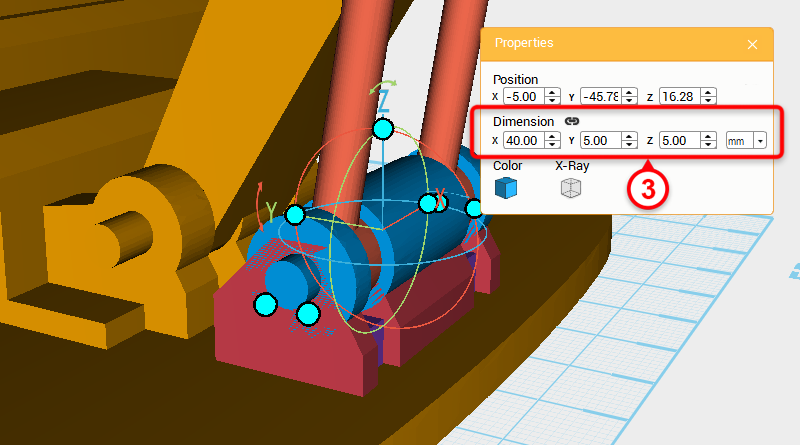 Select the cylinder in the image and click on the Clone button, then change the dimensions to X: 40,Y: 5,Z: 5mm. This will be a marker for the shaft later.
 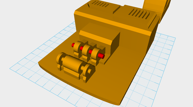 Apart from the Red cylinder in the image above, delete all of the parts in the Boom assembly.
 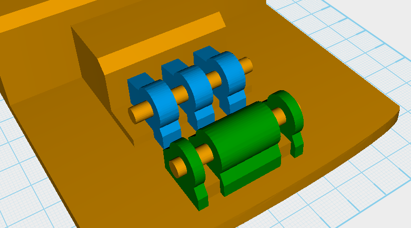 To make it easier to use the Hole function in the future, select the 6 blue parts shown above and group them together, then do the same for the green parts, making them into a separate group.
 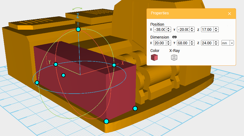 Next, to model the machine body’s left body chassis, create a cube and change its dimensions and position as shown above. Call this part the enclosure.
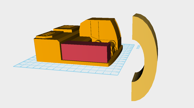
 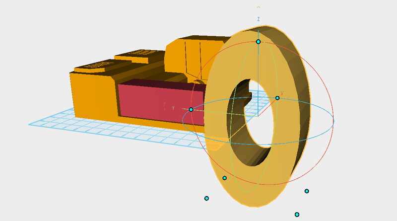 Face the front of the enclosure and cut out a curve, because this curve and the driver cab’s curve should be the same, create a tube and rotate it 90° along the Y axis, enlarge it so that it is the same size as the tube in the image above.
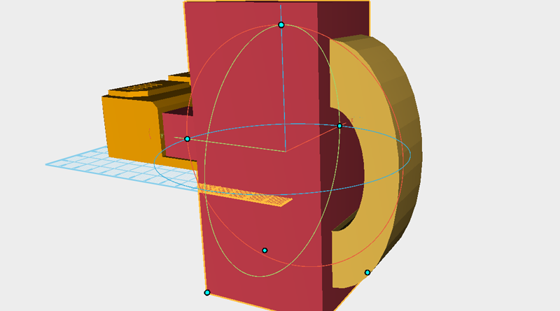
 Make a cube that is larger and use the Hole function to cut the tube in half.
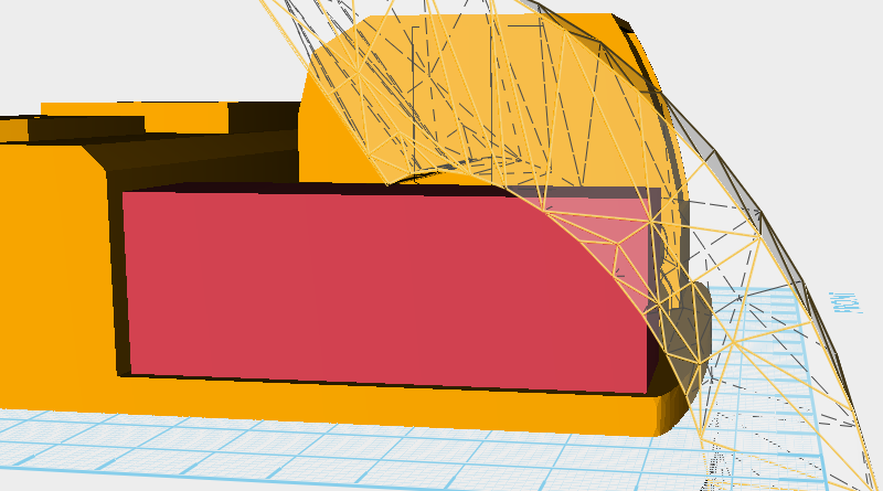
 After rotating the tube and moving to where to you want the curve, use the Hole function to cut a curve into the enclosure.
 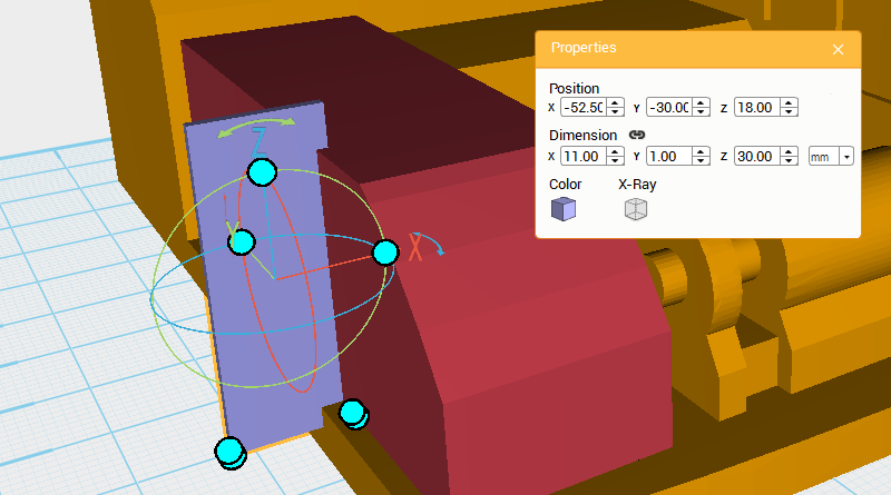 To give the model more detail, take the enclosure and cut away a groove. Make a cube and change its dimensions to X: 11,Y: 1,Z: 30 mm and position to X: -52.5,Y: -30,Z: 18. Refer to this part as the cutting part.
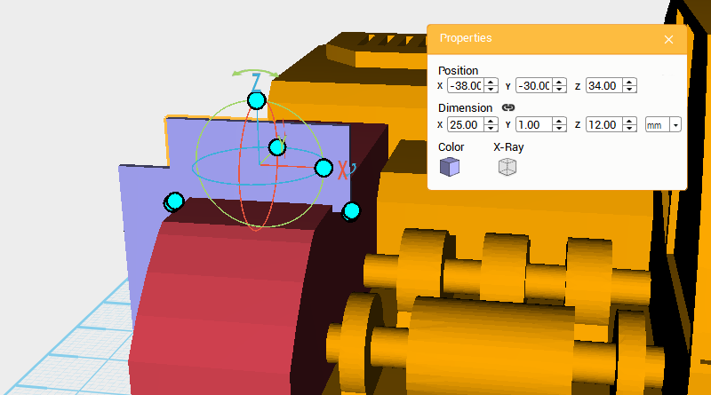
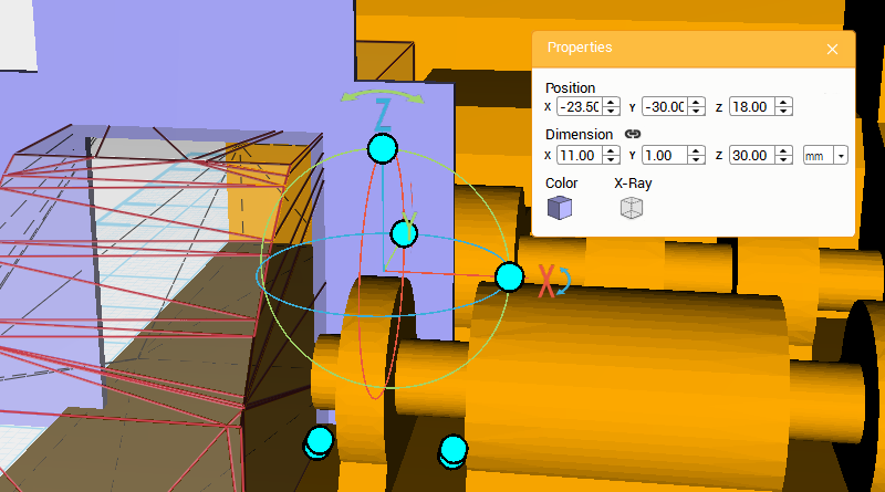 Copy the cutting part twice, refer to the image above for dimensions and position.
 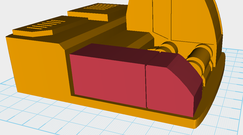 Use the three cutting parts and the Hole function to cut a groove into the enclosure.
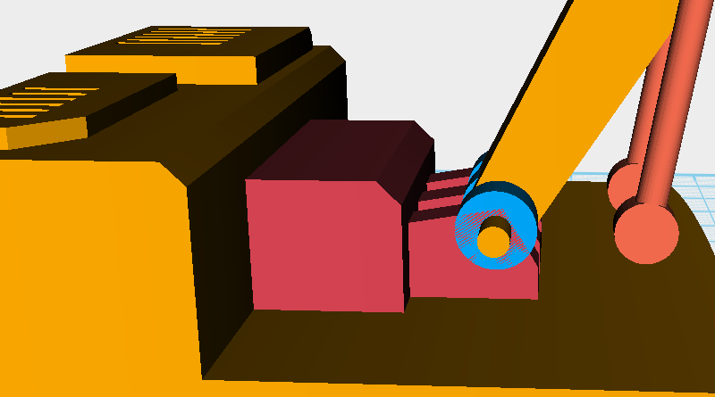
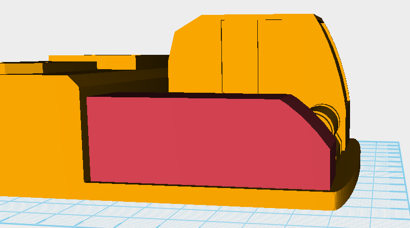
 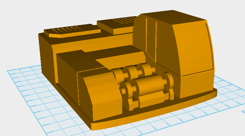 So far the enclosure should look like the above image.
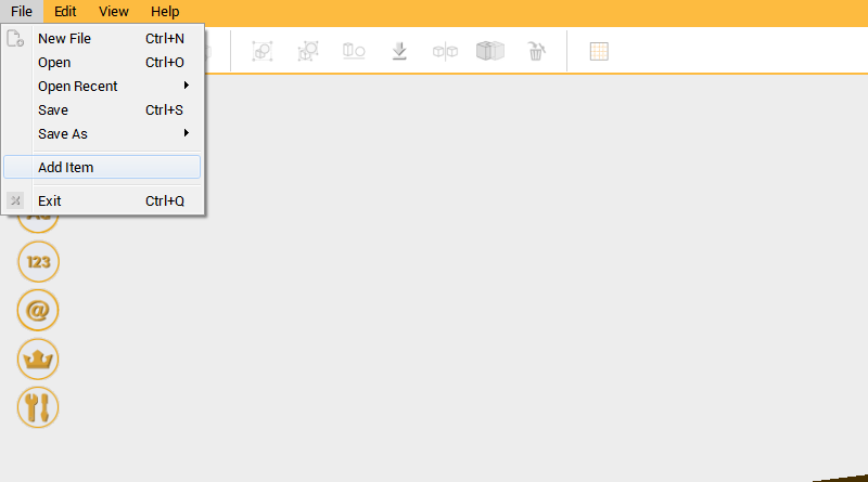
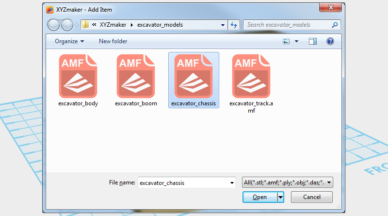 Go to the Menu bar, click on File and go to Add Item. In the file window select excavator_chassis.amf to add the chassis to modeling area.
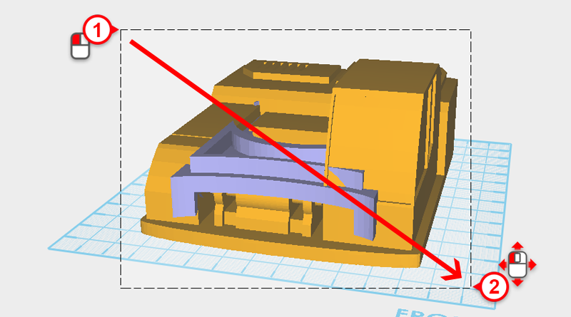
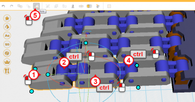
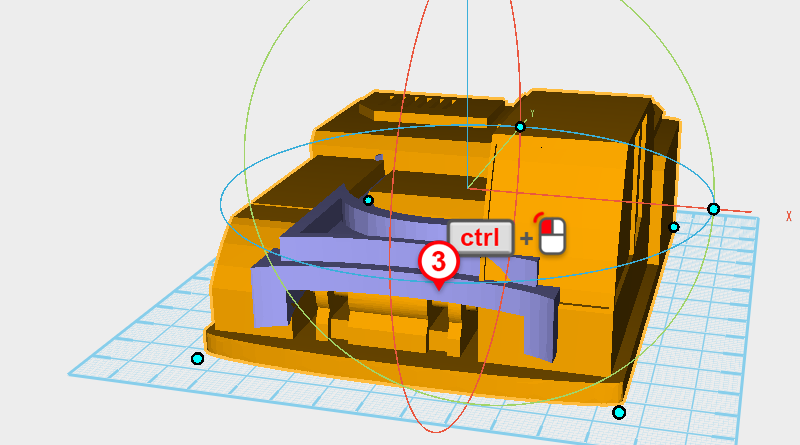 Drag select all the parts then press and hold down the ctrl key and click on the chassis assembly to deselect it.
 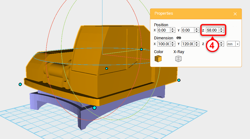 In the Properties window change the part’s Z axis position to 58.
 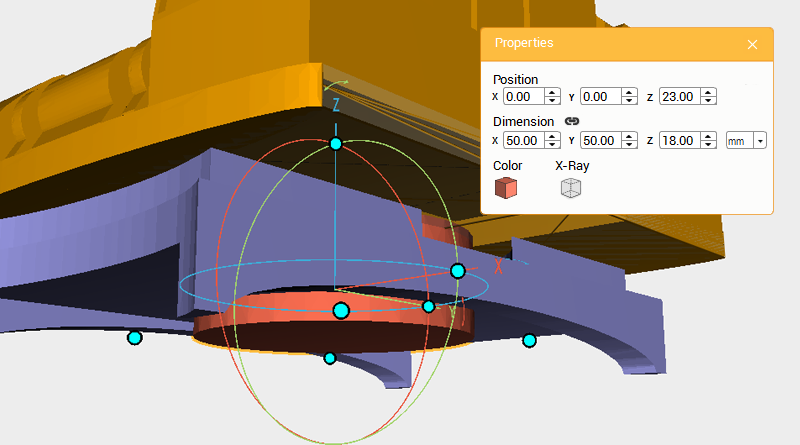 Turn off the modeling grid to better view the model, create a cylinder and change the part’s dimensions to X: 50,Y: 50,Z: 18 mm and position to X: 0,Y: 0,Z: 23. Later this will be an axis for the chassis assembly.
 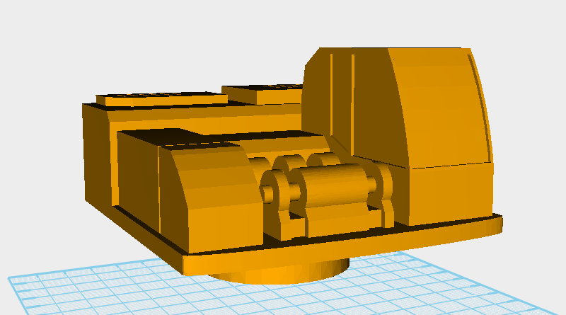 Delete the chassis assembly then save the file to finish the body assembly.