XYZmaker tutorial – the Excavator part 12
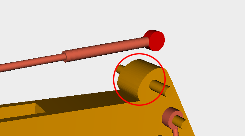 The red circle shows the area where the boom still needs to have space cut away for the hydraulic rod assembly.
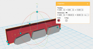
 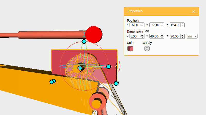 Create a cube and change its dimensions to X: 5,Y: 40,Z: 20 mm and position to X: -5,Y: -66,Z: 124. This will be a cutting part.
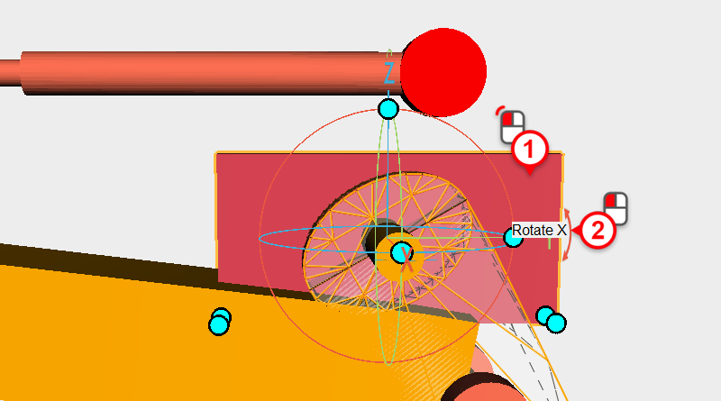
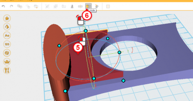
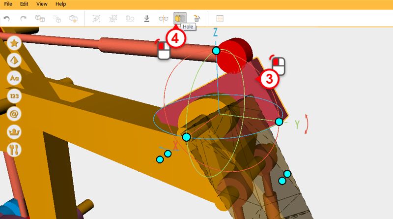
 Select the cutting part and click and drag the arrow next to the control orb Y axis down, rotating the part to 350°.
 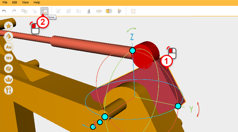 Because you need to cut two separate parts, click on the Clone button to duplicate the cutting part.
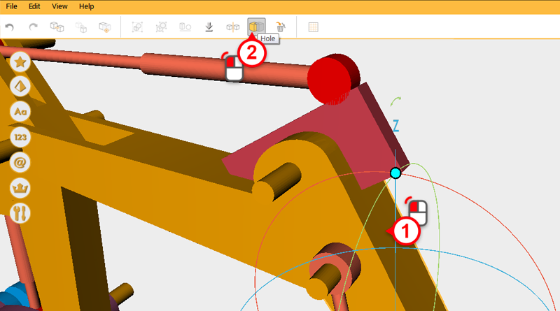
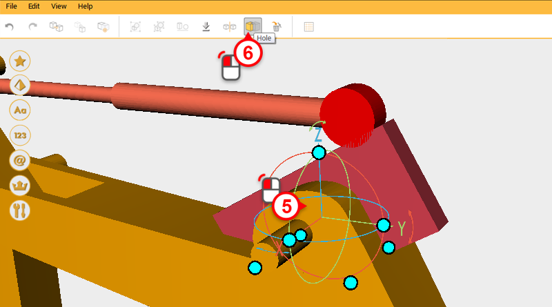
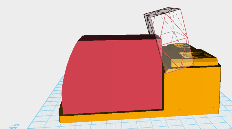
 Use two cutting parts and the Hole function to cut away from where the boom and digging arm connect.
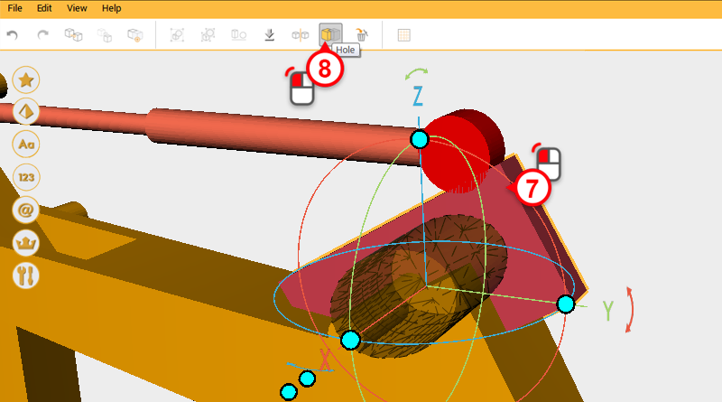
 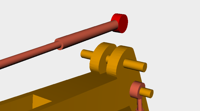 After cutting after from the boom, it should look like this.
 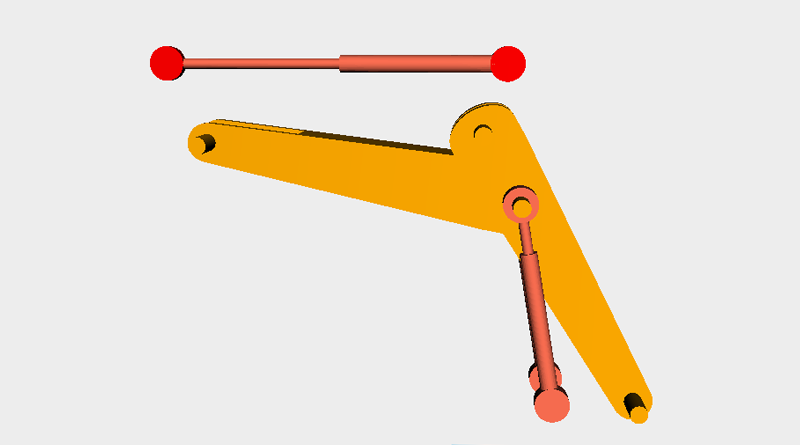 Lastly, delete all the boom parts, apart from the parts in the image above.
 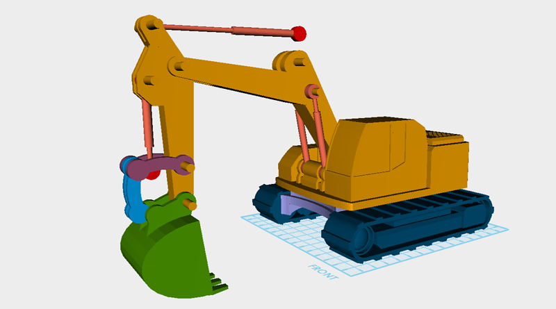 Prepare to import all the excavator parts into the same file, so that they can be assembled into the right formation. Go to Menu > Add Item and add excavator_arm.amf、excavator_body.amf、excavator_boom.amf、excavator_chassis.amf、excavator_track.amf to the file you are working on. These are all the parts for the excavator, now take all the moving parts and put them in their correct location to simulate what all the parts will look like after printing.
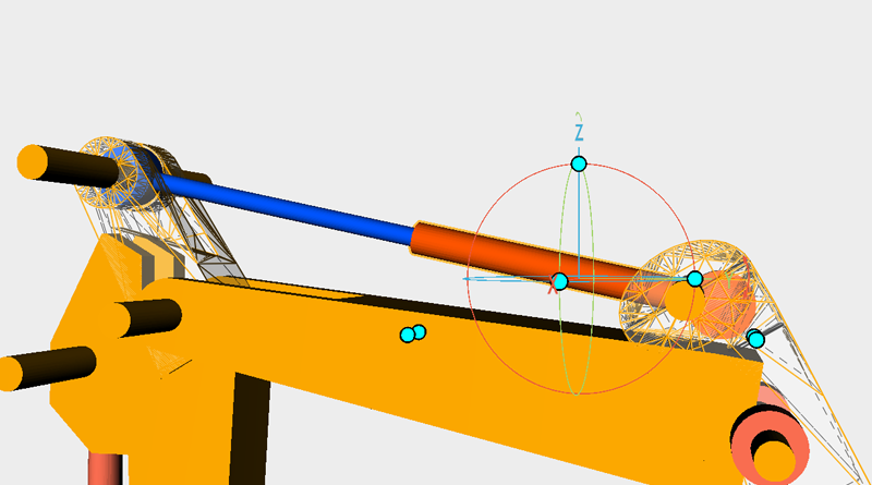
 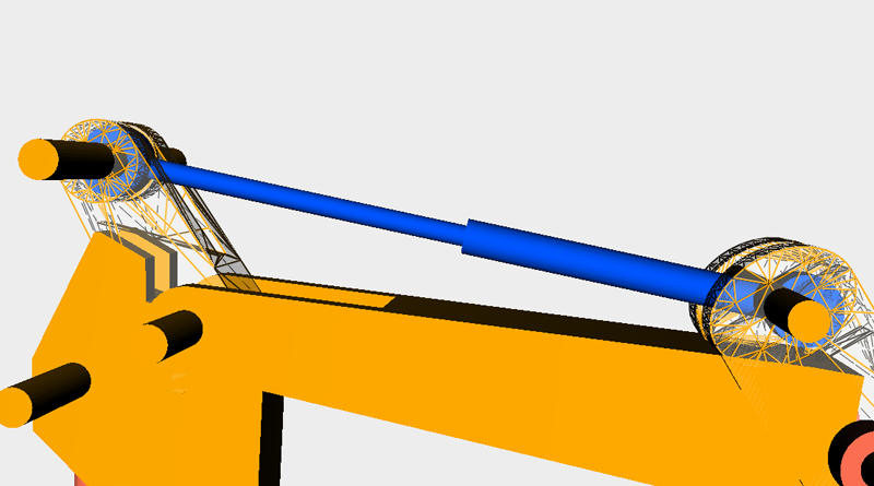 Select the blue hydraulic rod above and rotate it along the X axis, slowly adjust the Y and Z axis position so that the hydraulic rod is close to the same angle and position as the picture.
Tip: When rotating parts, hold down the Ctrl key to rotate in only increments of 1°
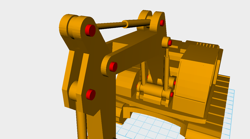
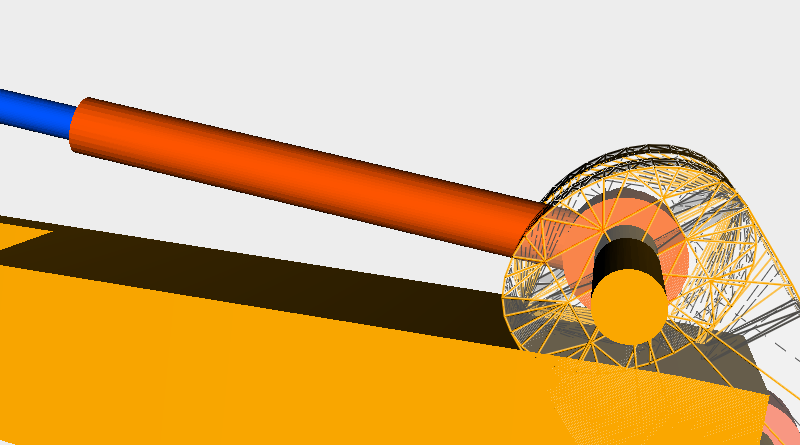 Select the only two orange cylinders above and adjust their Y and Z axis positions so that the hydraulic rod and boom are in the right locations.
 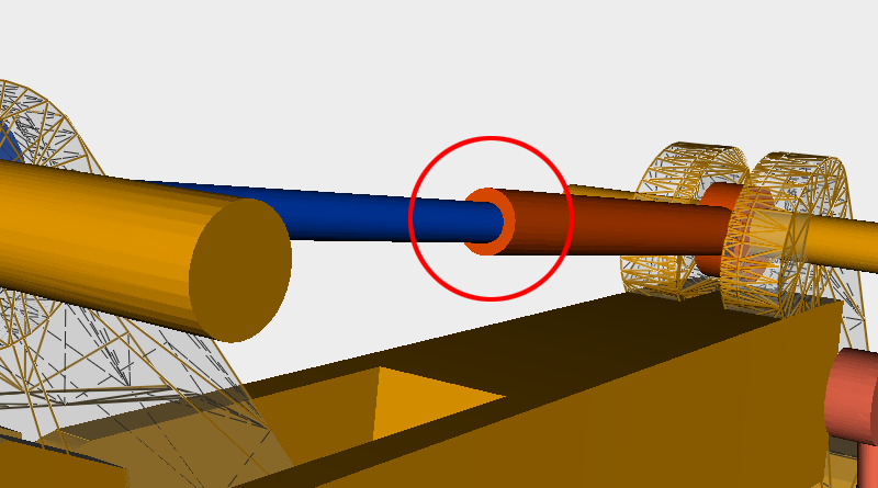 At the same time make sure that the hydraulic rod’s center connecting area doesn’t have too much deviation.
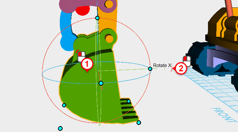
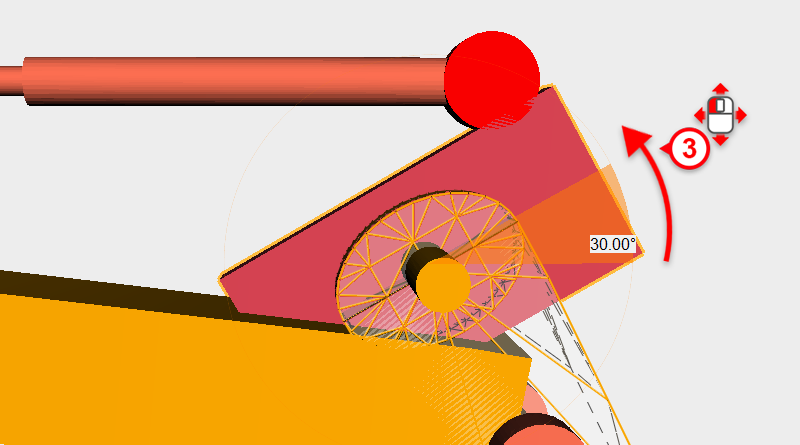
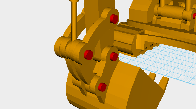
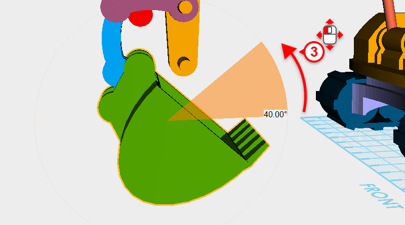 First decide on the bucket’s angle, then adjust the connecting part and hydraulic rod. Select the bucket, click and drag on the arrow next to the Y axis and rotate to part to 40°.
 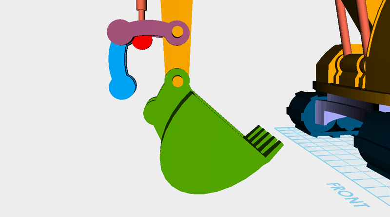 After rotating, the bucket and boom will separate, so adjust the bucket’s Y and Z axis position to make the bucket move to a suitable position.
 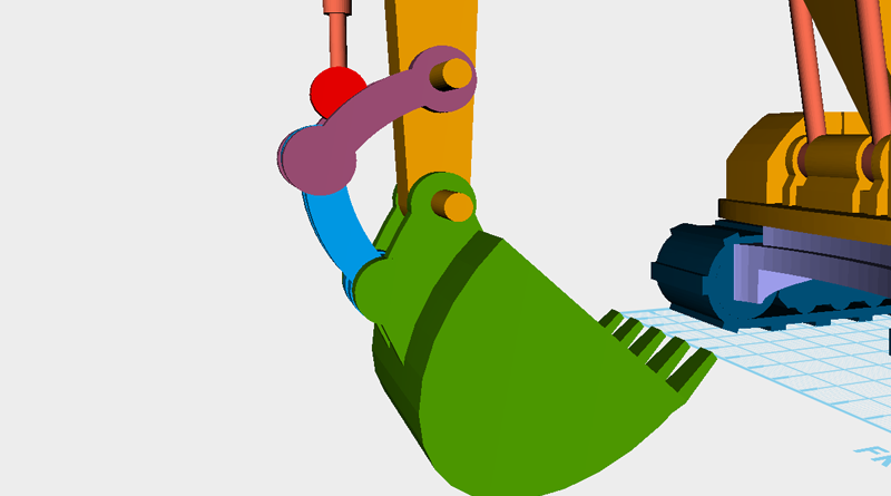 Adjust the hydraulic rod at the same as the previous step, take the four connecting parts and rotate them along their X axis, then slowly adjust the Y and Z axis position, so that the connecting parts are at the same angle and position as the picture.
Tip: The connecting parts need more detailed adjustment before finishing the whole model, use XYZmaker to confirm that the final assembled product doesn't have any errors and that is enough.
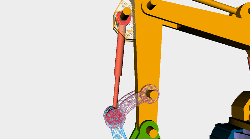 Next adjust the front of the hydraulic rod so that every part sits at the right angle and position.
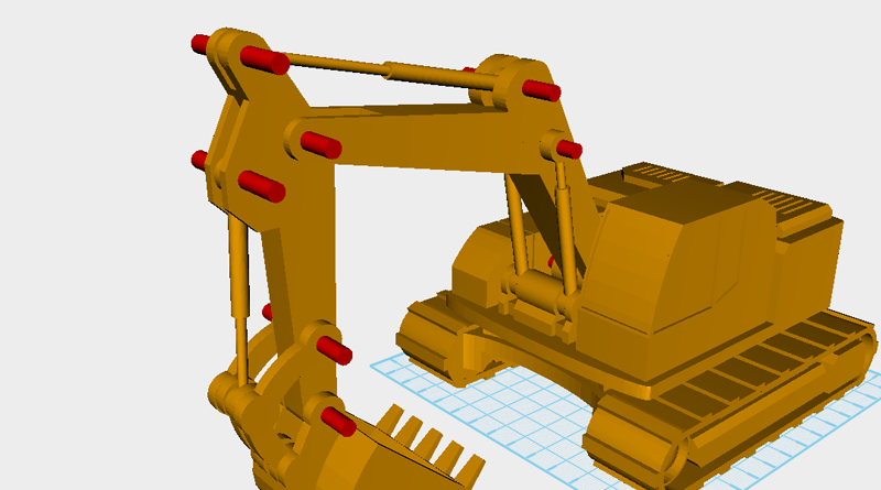
 Adjust the red colored cylinder’s X axis dimension so that the cylinders stick out from the surface by 2mm. These will be the shaft bolts.
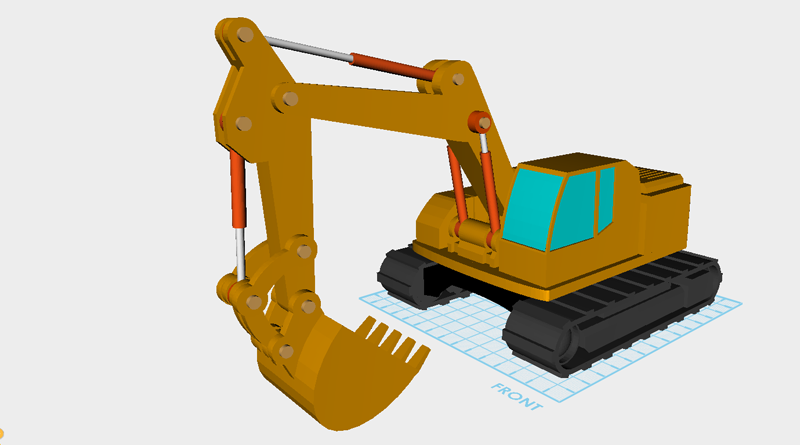
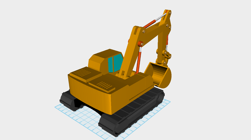 This is what the final excavator should look like, now you’re ready start planning how to print everything!