XYZmaker tutorial – the Excavator part 4
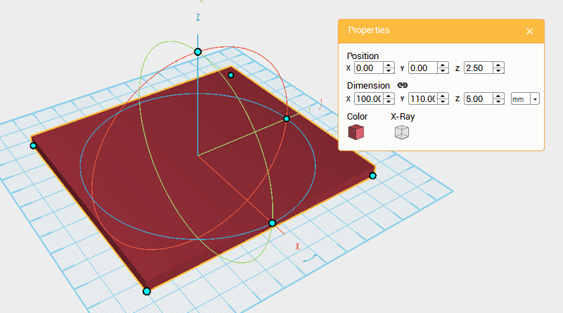 To start making the body, first create a cube and change its dimensions to X: 100,Y: 110,Z: 5 mm and position to X: 0,Y: 0,Z: 2.5. Call this part the floor.
 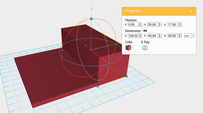 Create another cube and change its dimensions to X: 100,Y: 40,Z: 35 mm and position to X: 0,Y: 60,Z: 17.5. Call this part the engine.
 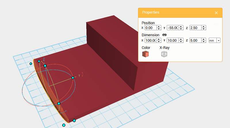 Create a cylinder and change its dimensions to X: 100,Y: 10,Z: 5 mm and position to X: 0,Y: -55,Z: 2.5. This will add a front edge to the floor.
 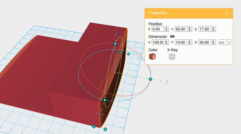 Create another cylinder and change its dimensions to X: 100,Y: 10,Z: 35 mm and position to X: 0,Y: 55,Z: 17.5. This will add a rear curve to the floor and engine.
 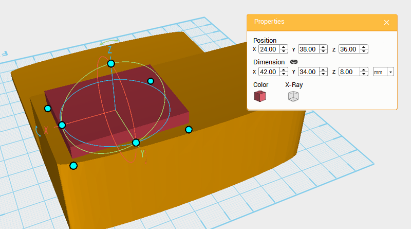 Create a cube and change its dimensions to X: 42,Y: 34,Z: 8 mm and position to X: 24,Y: 38,Z: 36.
 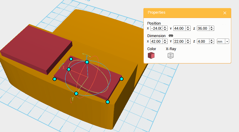 Create another cube and change its dimensions to X: 42,Y: 22,Z: 4 mm and position to X: -24,Y: 44,Z: 36 to add engine details.
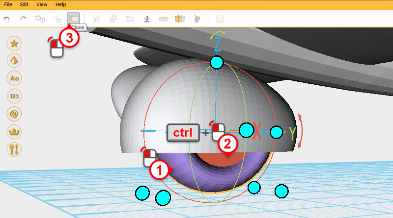
 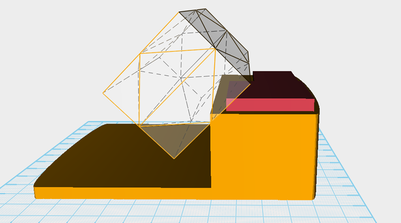 Clone the engine, slightly enlarge the X axis dimension, then after rotating the part 45 ° along the X axis, move it to a similar position as shown in the image above. Call this the cutting part.
 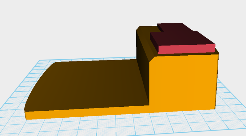 Use the cutting part and the Hole function to cut a chamfer in the engine.
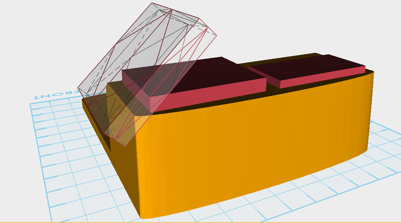
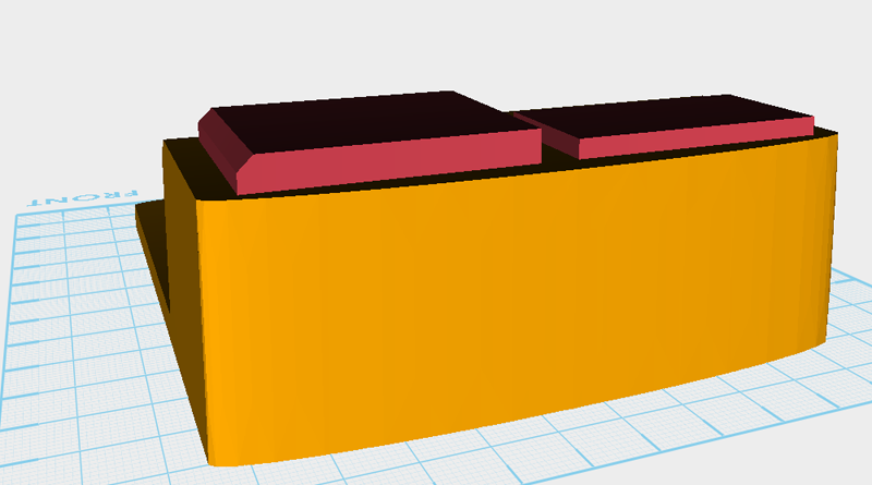
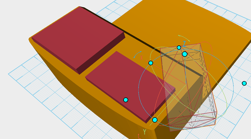
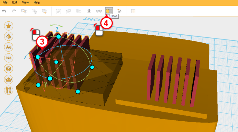
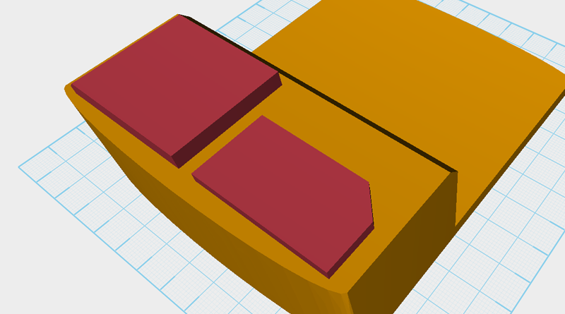 Using the same method mentioned earlier, follow the images above to cut angles into the cube on top of the engine.
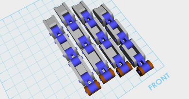
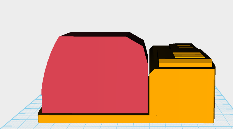
  Next you need to cut out some vents to make the model more realistic. Create a cube and change its dimensions to X: 1.5,Y: 20,Z: 20 mm and position to X: 38,Y: 42,Z: 46. Call this part the cutting part.
 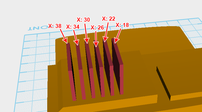 Copy the cutting part 5 times using the Clone button and as shown in the image above, incrementally change the X axis position of each part by 4mm so that the parts are equally spaced along the X axis.
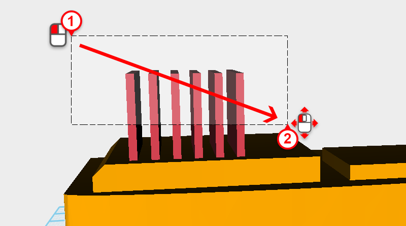
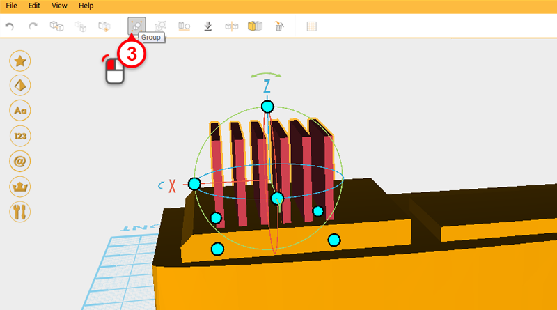 Drag select all the cutting parts and click on the Group button.
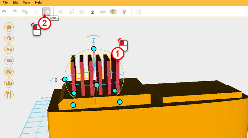
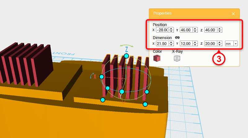 Clone the grouped cutting parts and change the group’s overall dimension to X: 21.5,Y: 12,Z: 20 mm and position to X: -28,Y: 46,Z: 46.
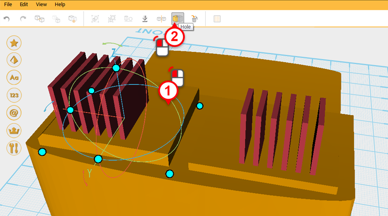
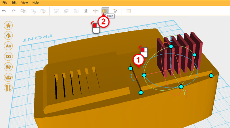
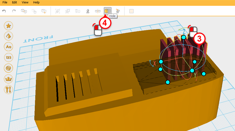
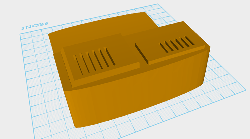 Use the two cutting groups and the Hole function to cut ventilation holes in the two cubes on top of the engine.
 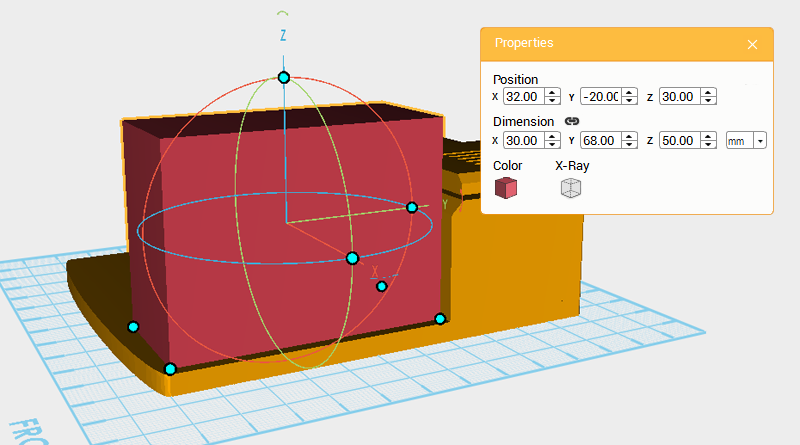 Next you need to make the driver cab, create a cube with the dimensions X: 30,Y: 68,Z: 50 mm and position X: 32,Y: -20,Z: 30. Call this part the driver cab.
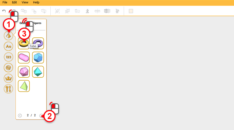
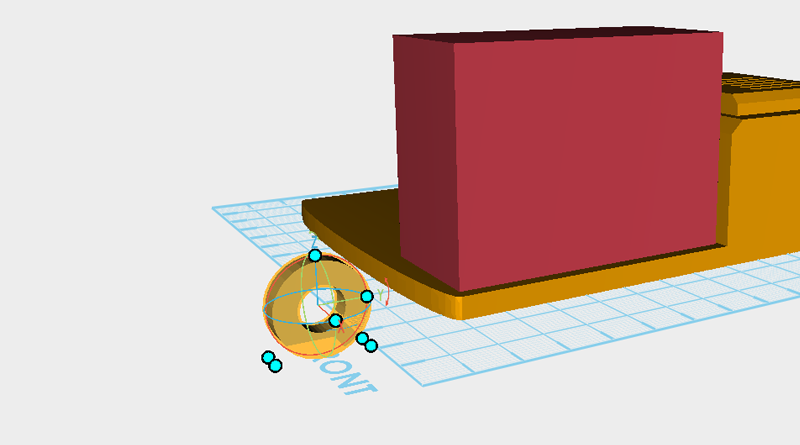 Create a tube and rotate it 90 degrees along the Y axis, then move it to the front of the driver cab.
 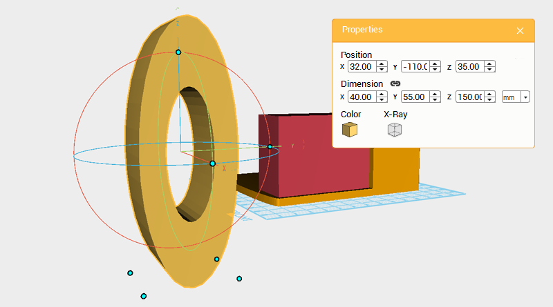 Change the tube’s dimensions to X: 40,Y: 55,Z: 150 mm。
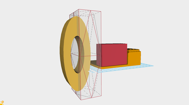
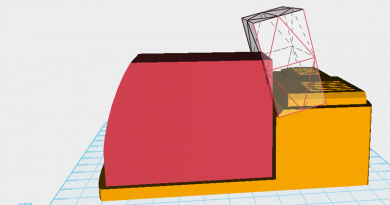
 Create a cube then move and enlarge it, as shown in the image above, until it covers the back half of the tube.
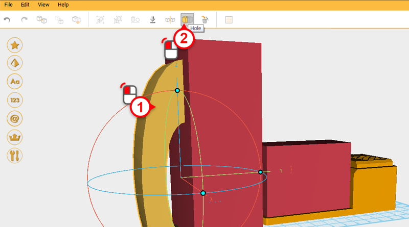
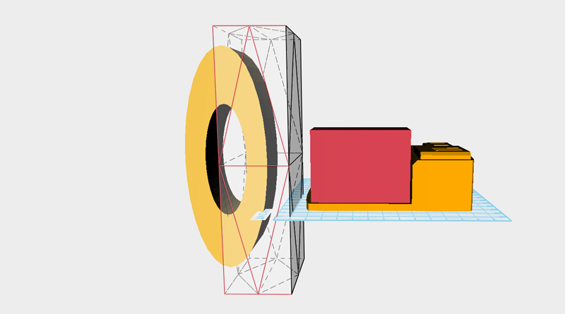
 Use the cube and the Hole function to remove the back half of the tube.
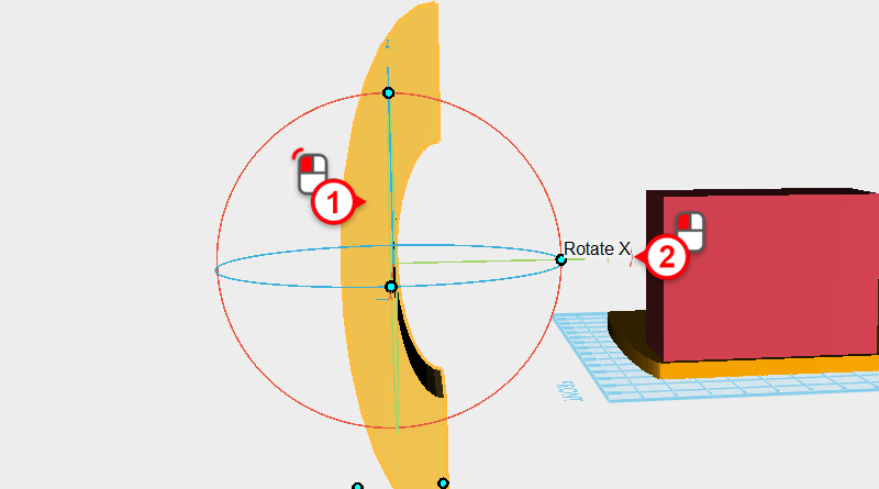
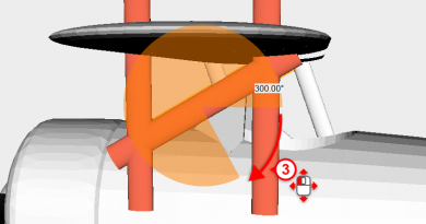
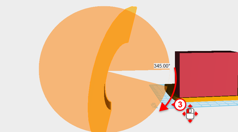 Select the remaining part of the tube and click and hold the Y arrow in the control orb, then drag the mouse down and rotate the part 345°. Call this part the cutting part.
 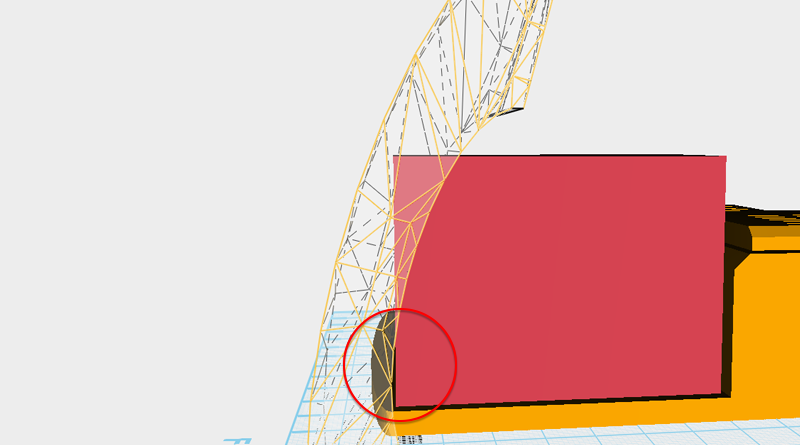 Next, move the cutting part so that it intersects with the front of the driver cab, and prepare to use the inside curve to cut a curve into the driver cab. You need to make sure that the two parts don’t overlap near the bottom of the cube as shown in the image above.
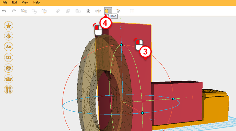
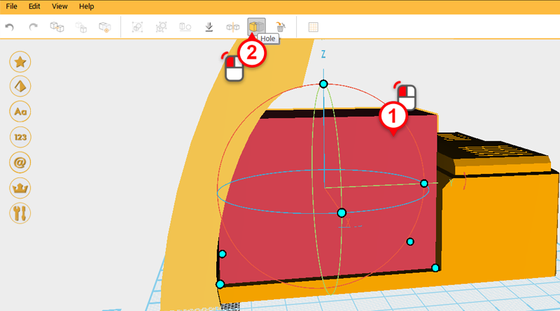
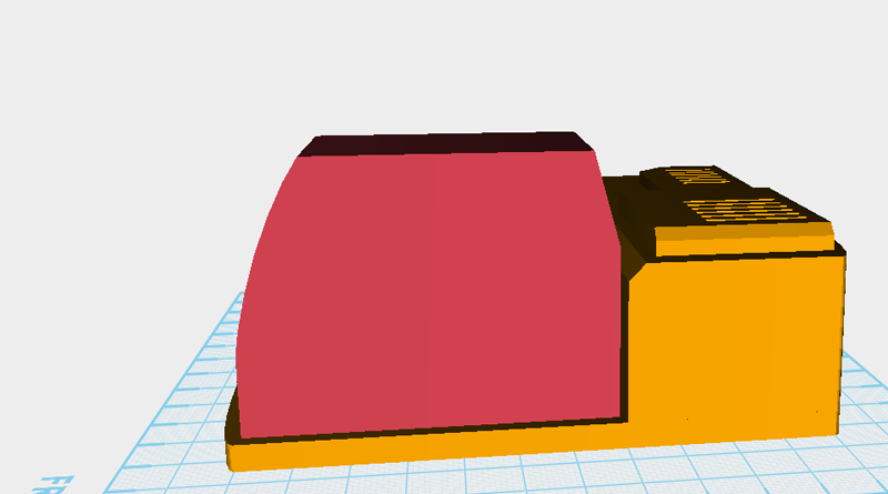
 Use the cutting part and the Hole function to cut a curve into the front of the driver cab.
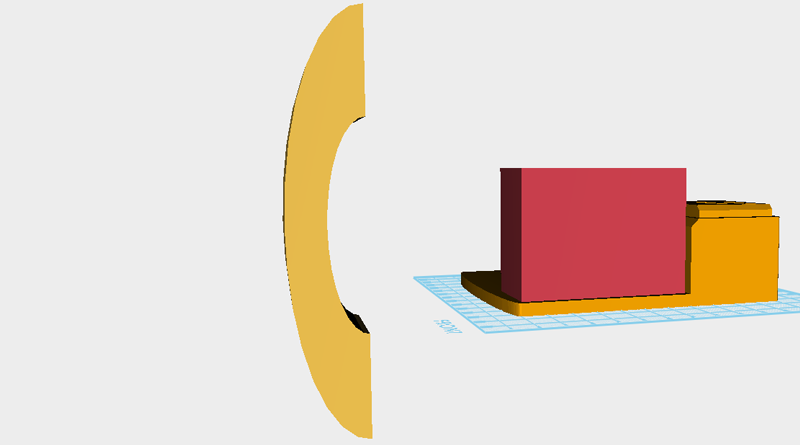
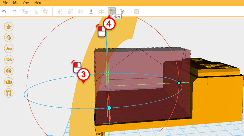
 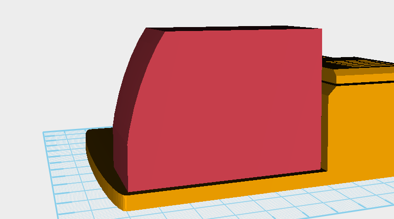 After cutting the part should look as above.
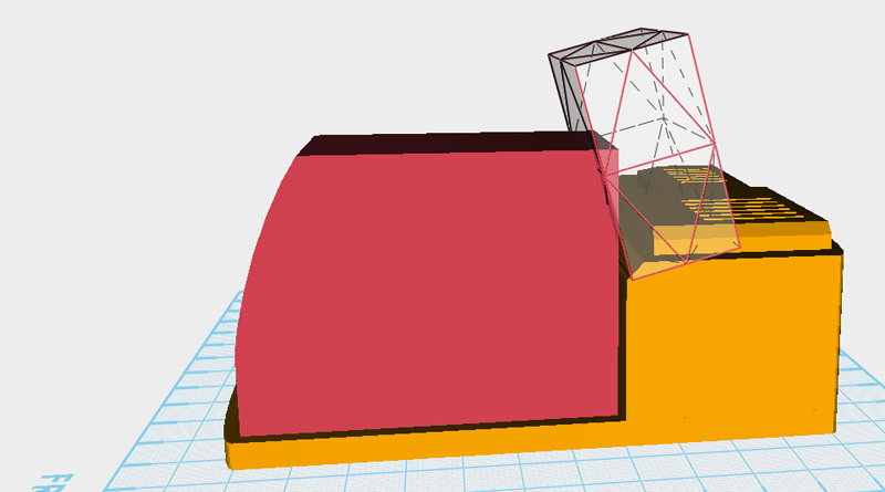
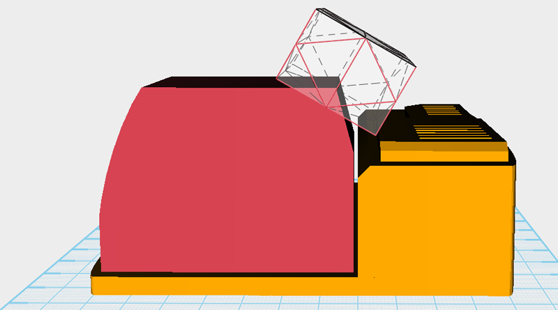
 Next, create two cubes, rotate them, and move them to create two chamfered edges in the drive cabin.